LogoTurtle
A programmable floor turtle
With Brian Silverman and Erik
Nauman, we adapted an Instructable Arduino floor turtle robot to run
Brian's LogoTurtle.
These instructions will teach you
how to construct and begin programming your own LogoTurtle robot.
"The idea of mucking about in
programming is, for better or for worse, not very popular in grown up
computer science. Programming these days has become more of an
engineering discipline with the idea being that you should do things
once and do it right. Logo is and always was about debugging. Before
the do it right stage there are always dozens if not hundreds of do it
not-quite-right stages. This iterate-iterate-iterate then iterate again
is not very prevalent in work with microcontrollers. LightLogo and
TurtleLogo try to make microcontroller programming interactive but they
are far from the mainstream."
Brian Silverman
3D Printing and Assembly
3D print the models at .3mm layer
height, 2 shells, 25% infill, with
the exception of the chassis, which should be 3D printed at 35% infill.
Insert the 5/8" ball
bearing as soon as the 3D printer stops
for an easy, perfect fit. The ball may not rotate when the turtle is
moving but that is fine.
This variation of the robot uses a
different microcontroller than the
original version. Please follow steps 3 through 6 in the original
instructions to assemble the 3D printed parts and attach the
stepper motors.
Consider using a small piece of
wood to shim between the 3D printed stepper motor mounts. This reduces
the amount of bowing in the chassis and helps keep the wheel base
measurement consistent across turtles. When you calibrate your turtle
later, you can get the turtle to turn almost perfectly 90 degrees by
finding the correct length of shim that the robot needs.
Remove the 3D printed pen
holder/servo bracket so you have access to the complete underside of
the turtle before you build the electronics.
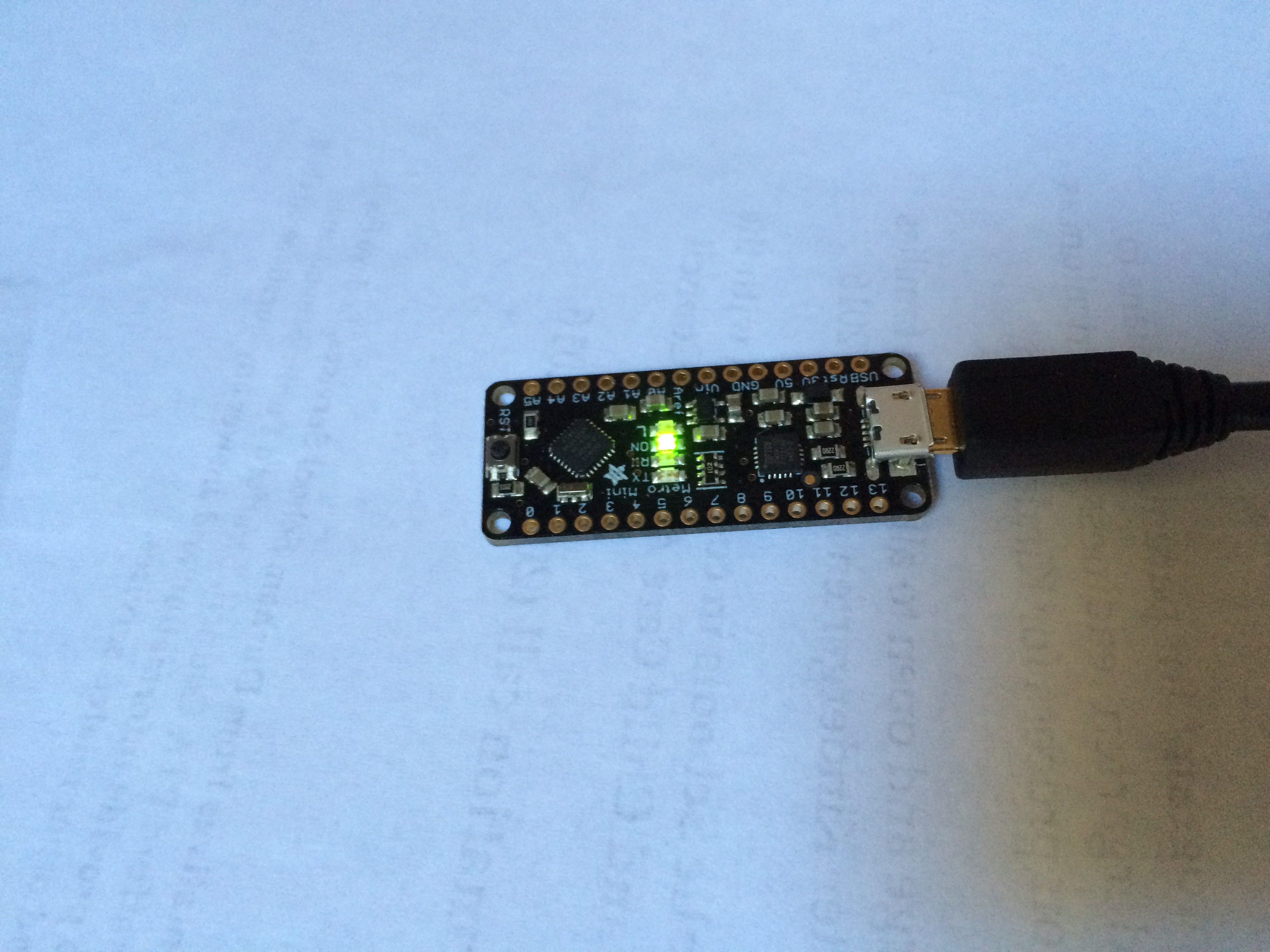
The turtle's electronics are built
around the affordable Adafruit Metro Mini microcontroller.
Additionally, please purchase the
following parts:
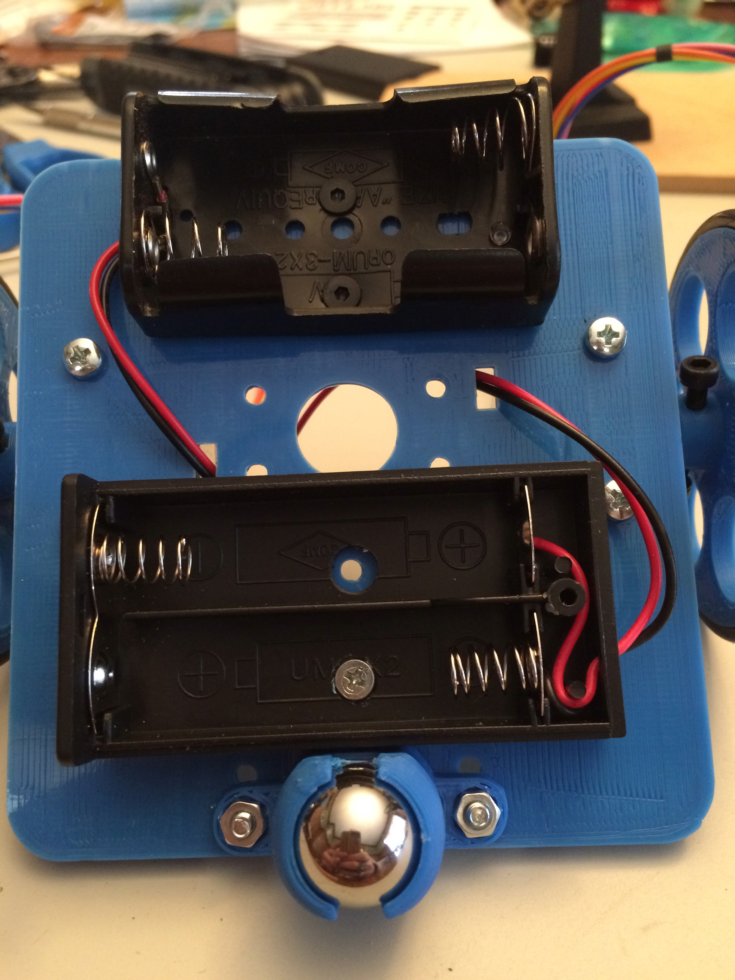
Attach the battery holders
according to the Instructable directions.
Once the battery holders are
attached, route the wires through the slots on the underside of the
turtle.
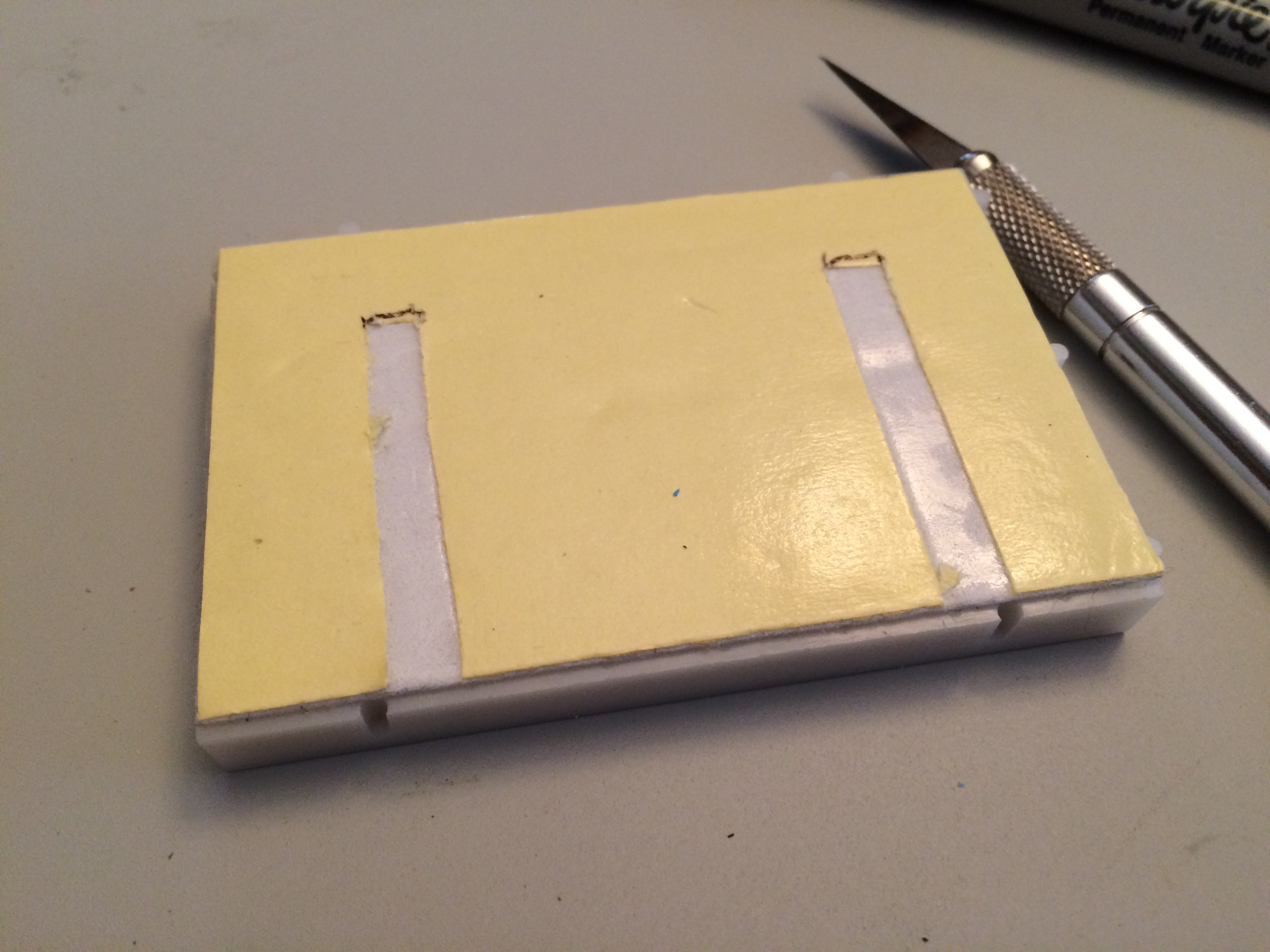
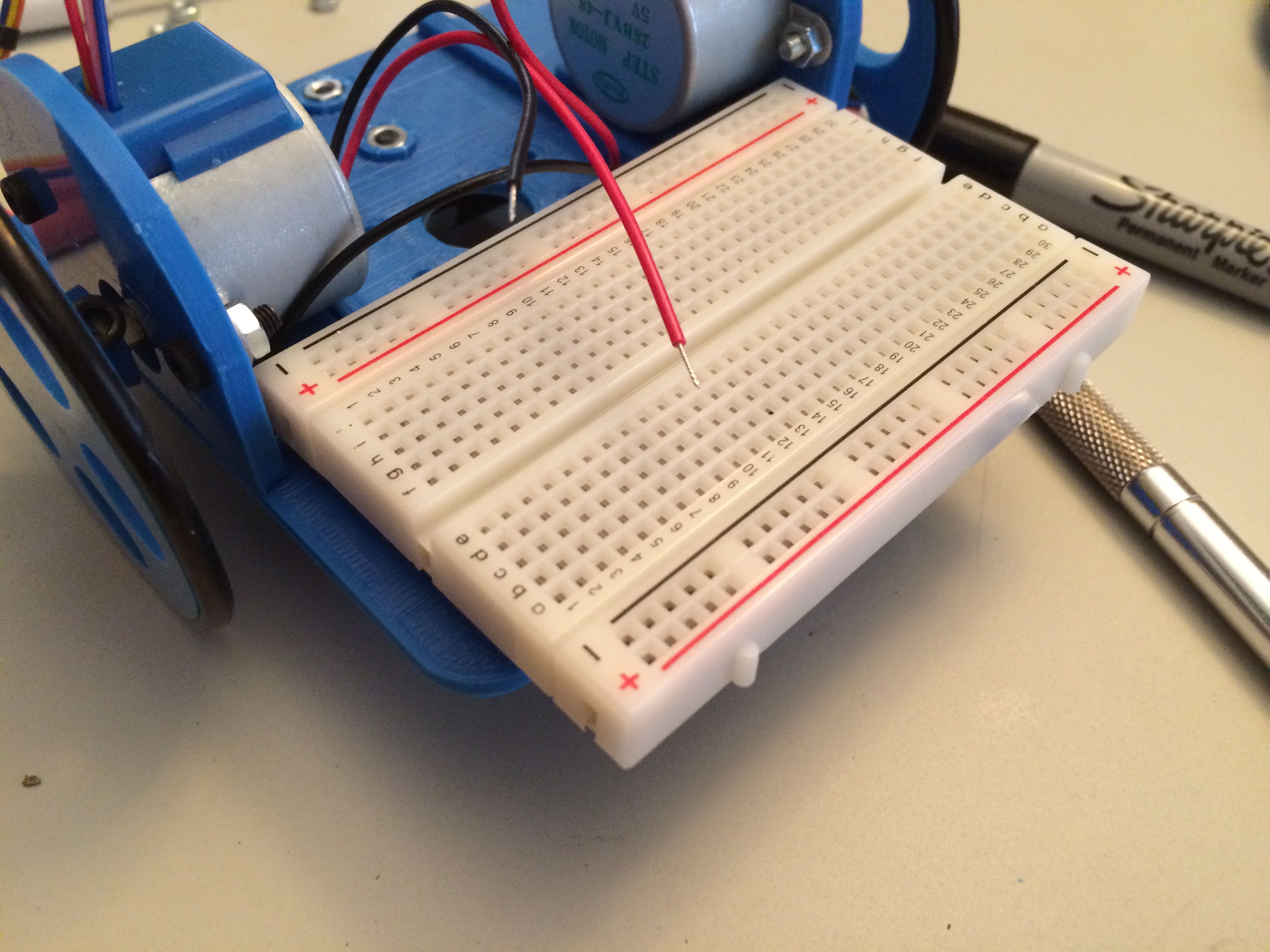
Using the rails on the top of the
chassis as a guide, use a knife to score the backing on the breadboard
without cutting the adhesive underneath. Remove the backing and attach
the breadboard to the top side of the chassis. Orient the breadboard so
the higher numbers are towards the right side. The breadboard will hang
out over the rear of the turtle.
Building the Electronics
If you have never used a breadboard to assemble a circuit, please see this tutorial to familiarize yourself.
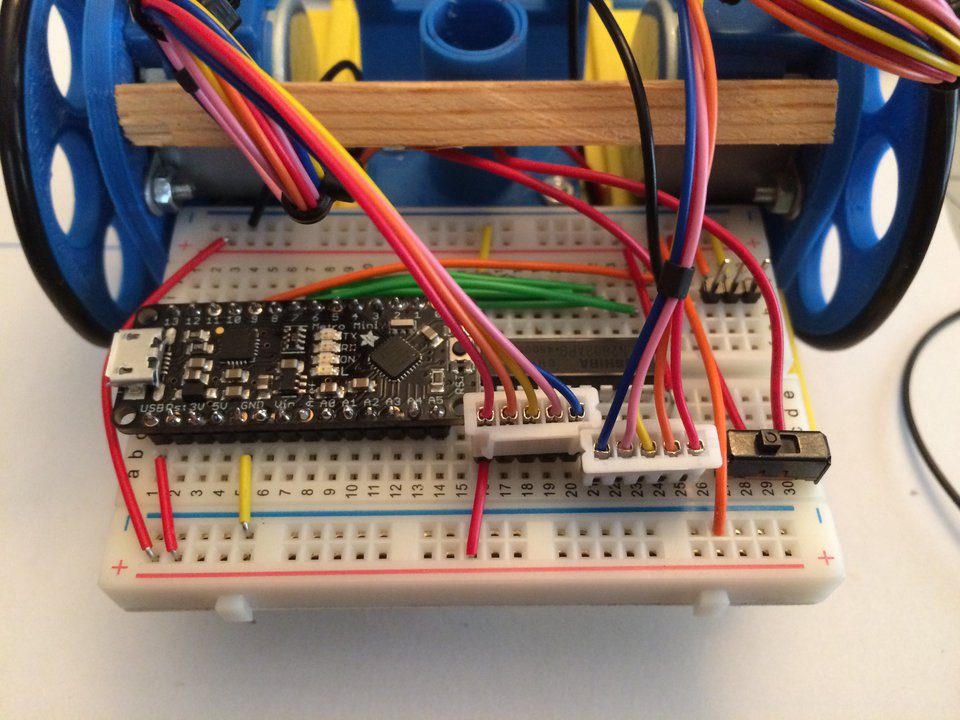
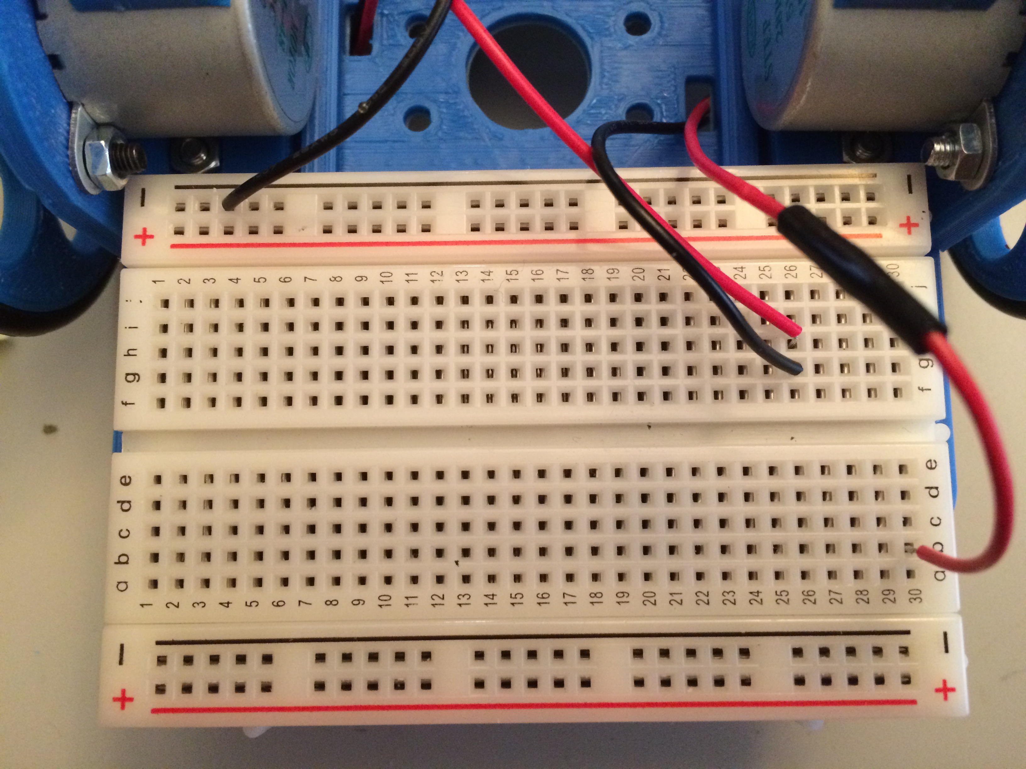
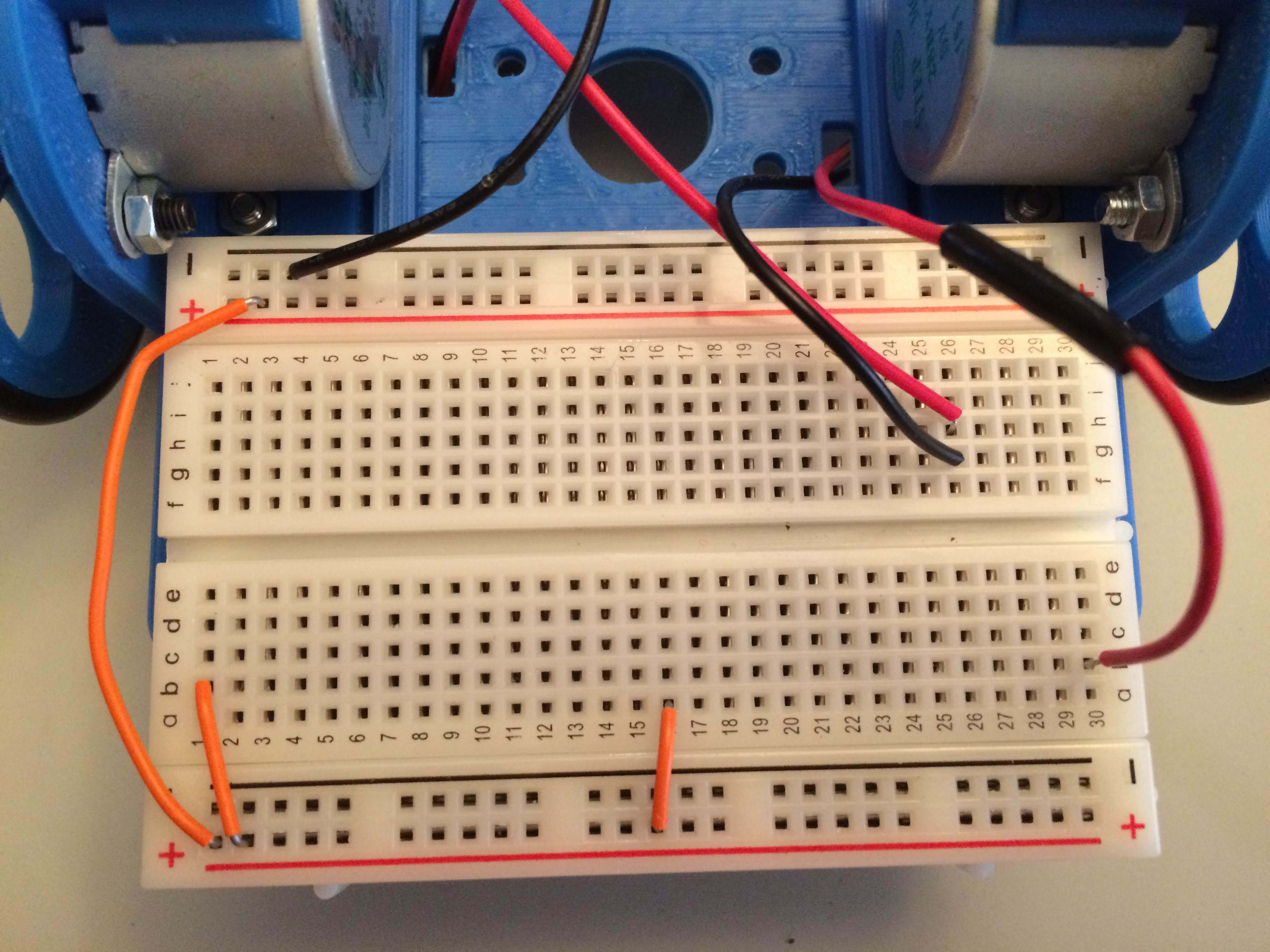
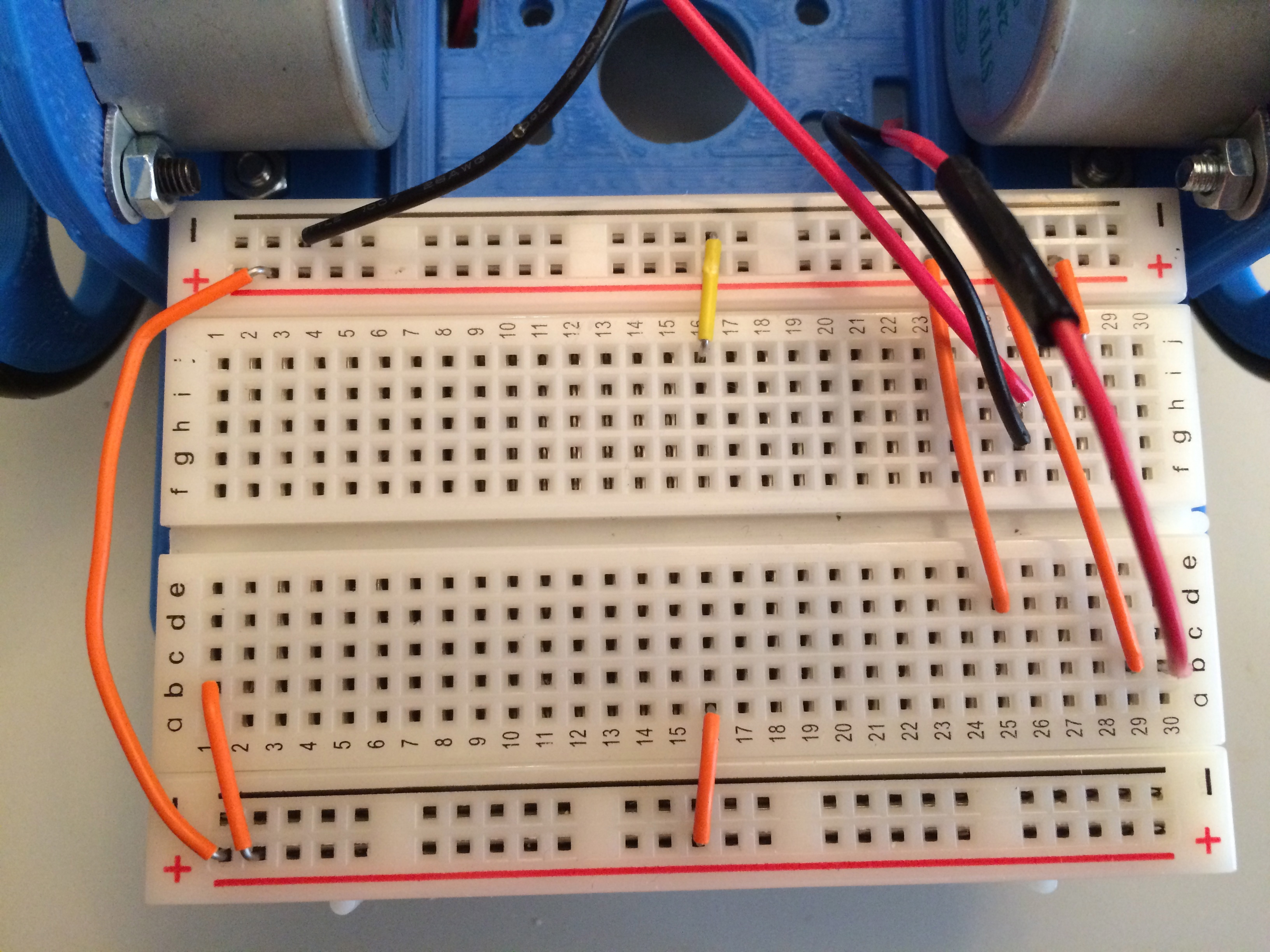
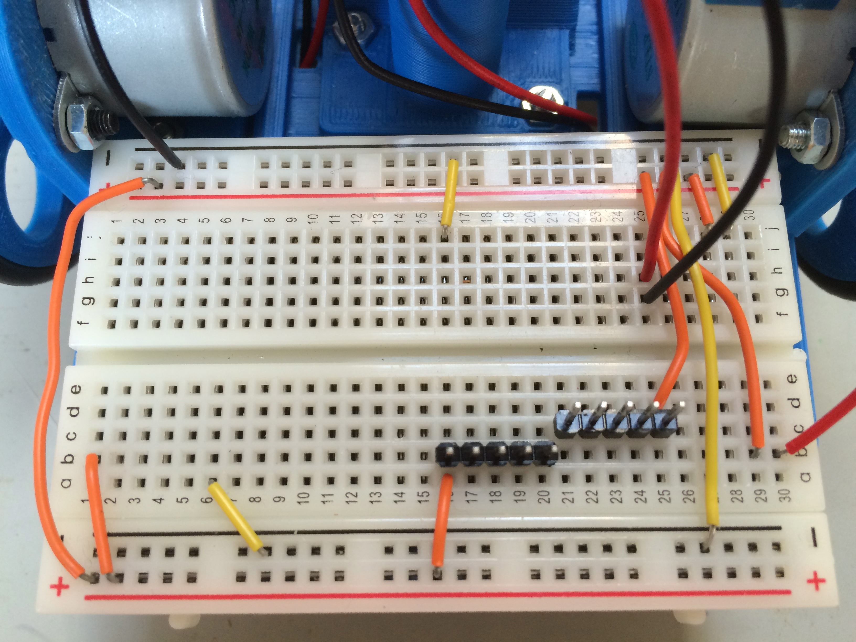
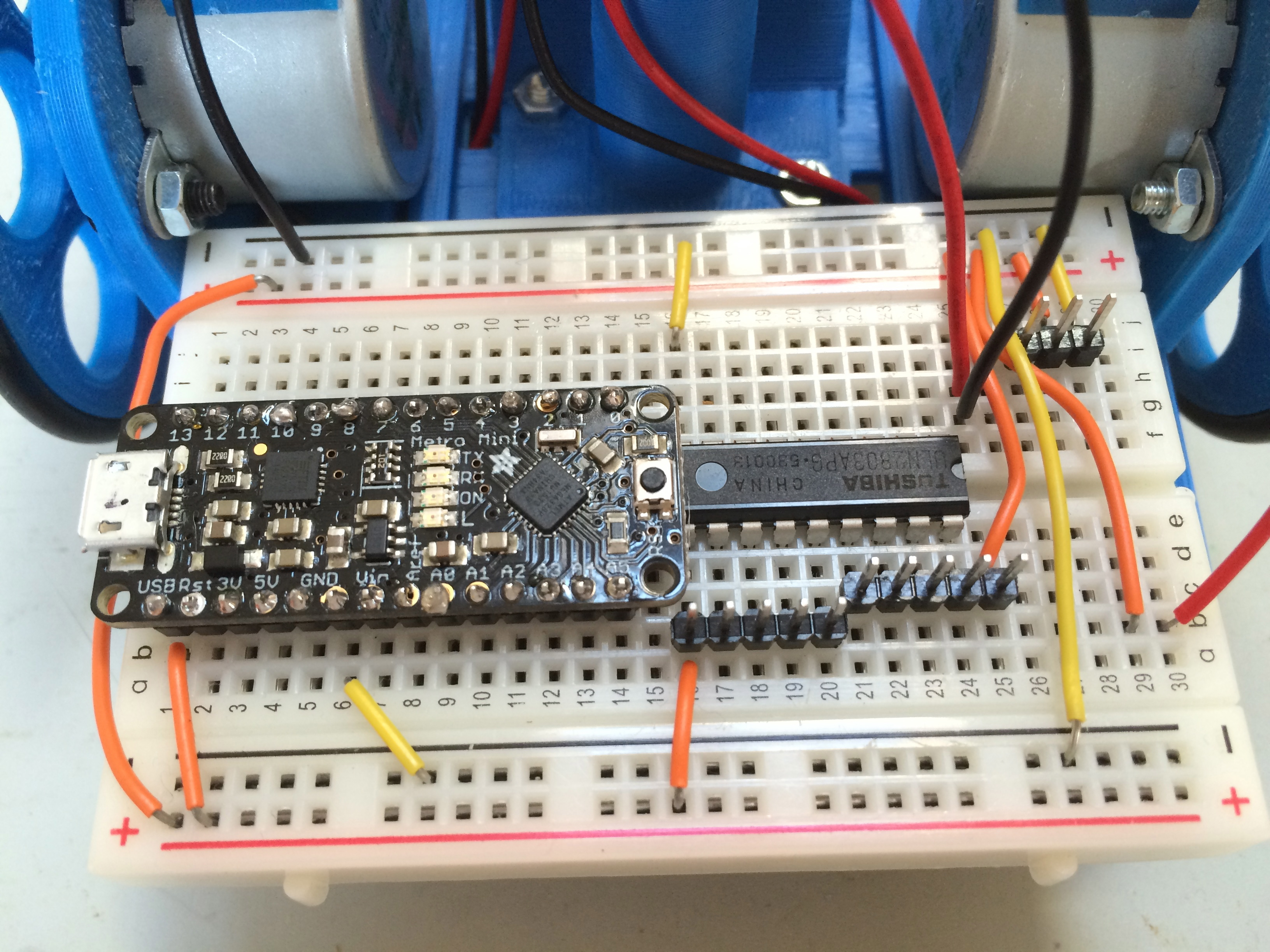
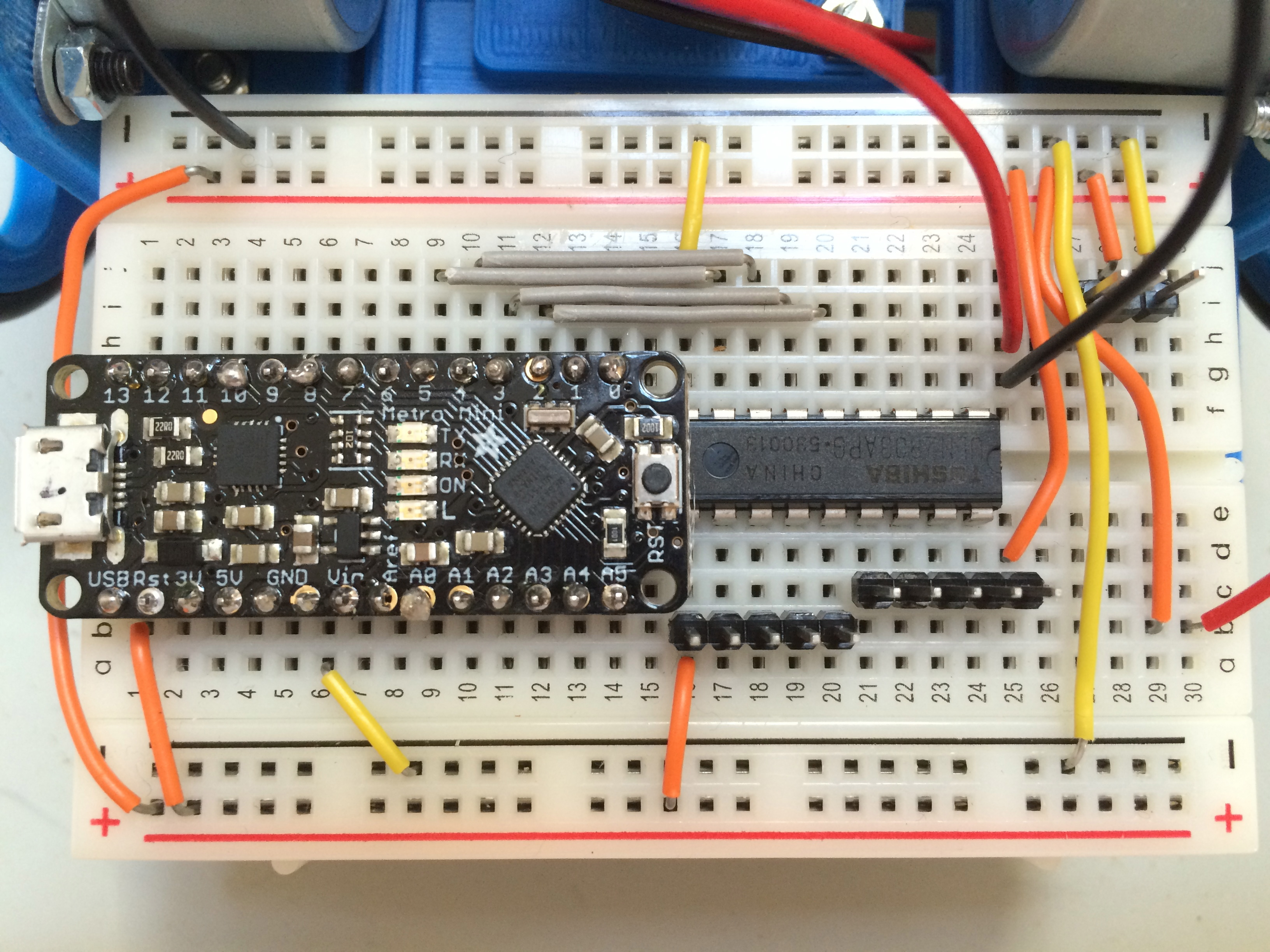
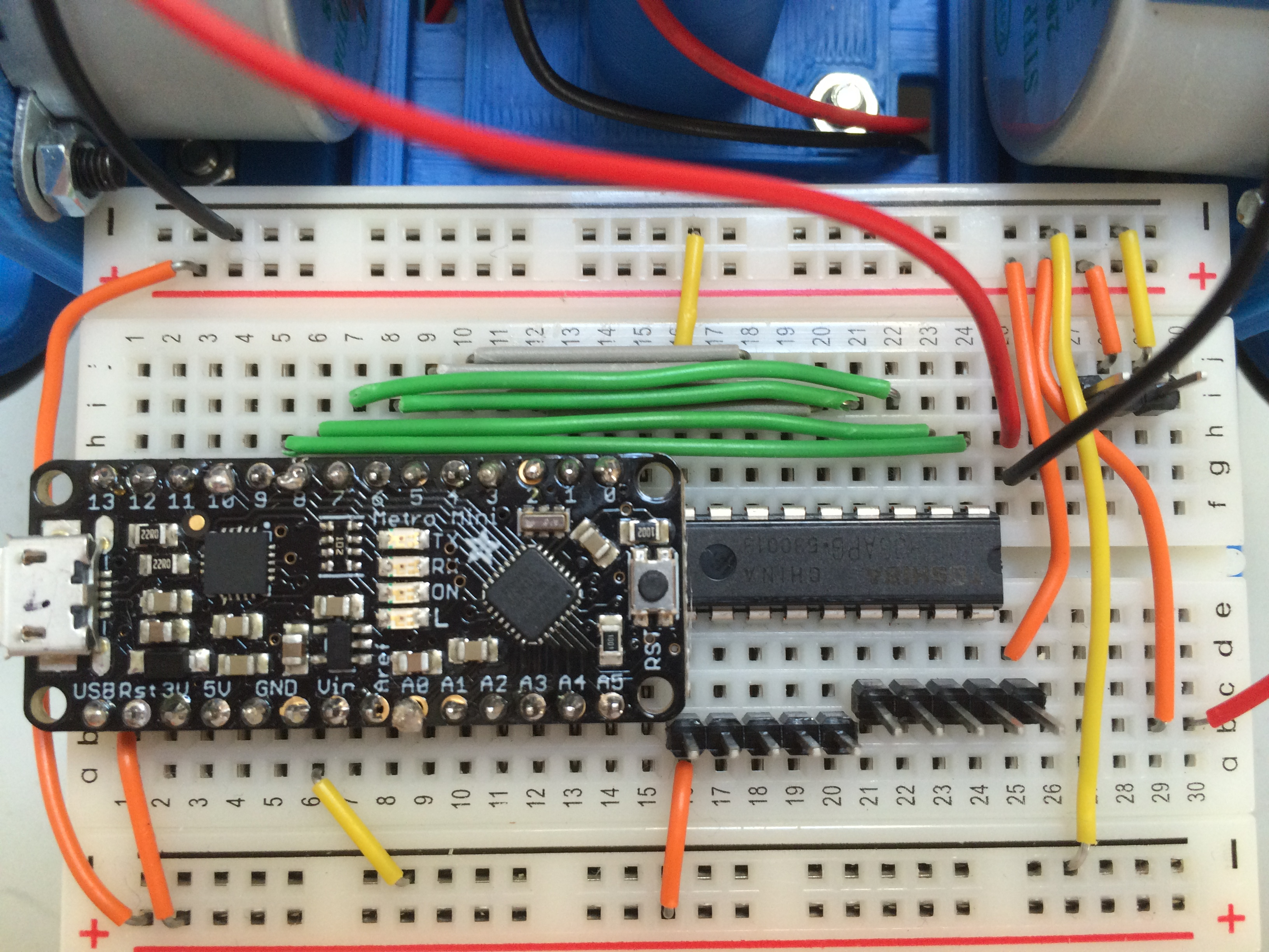
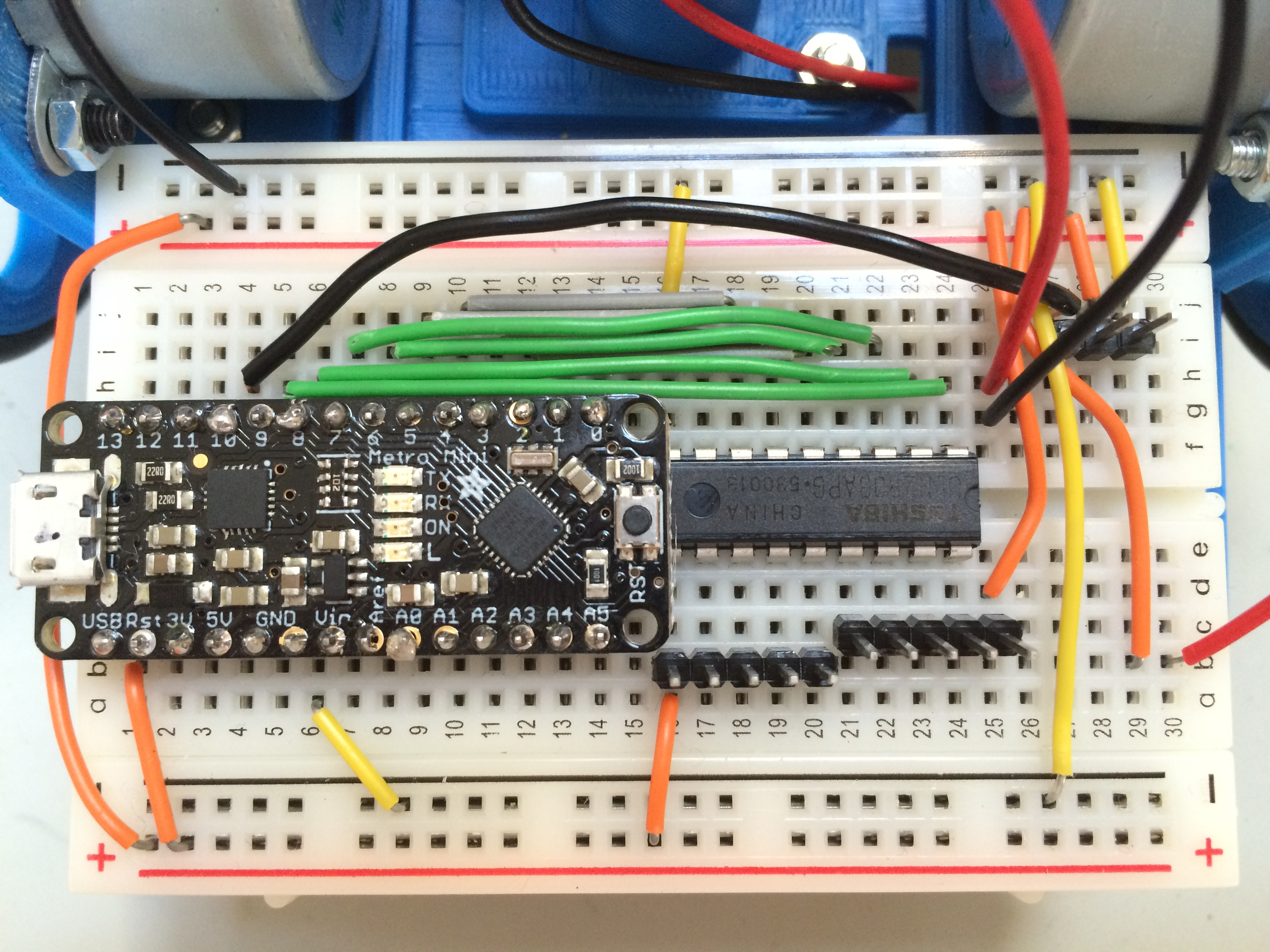
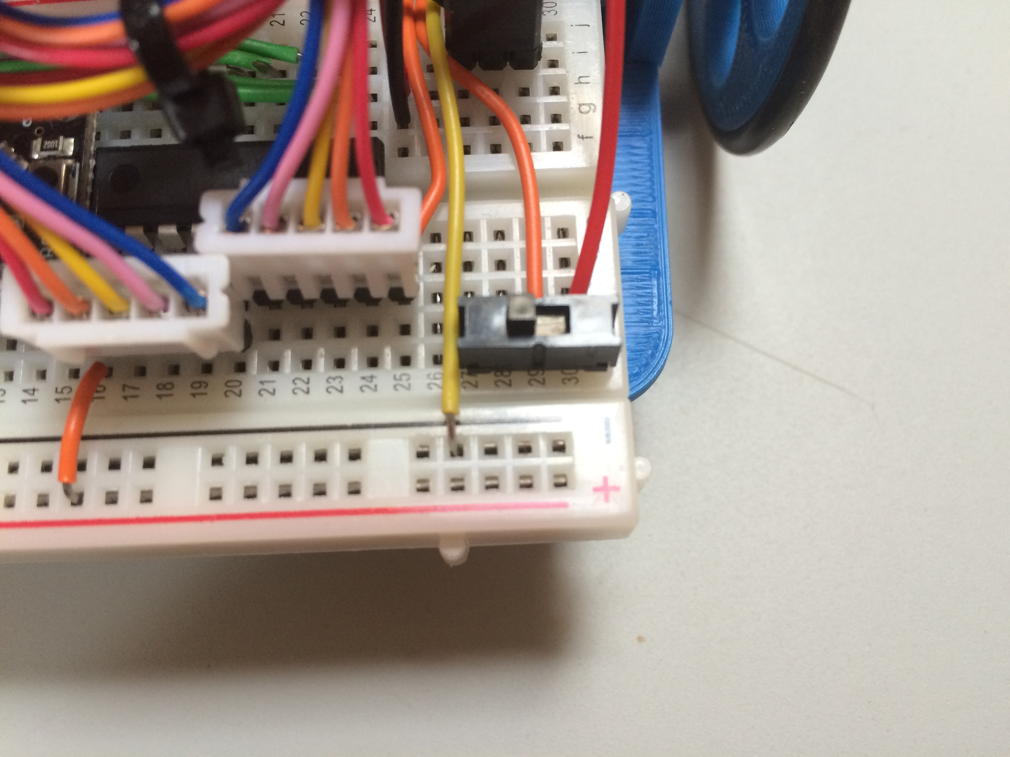
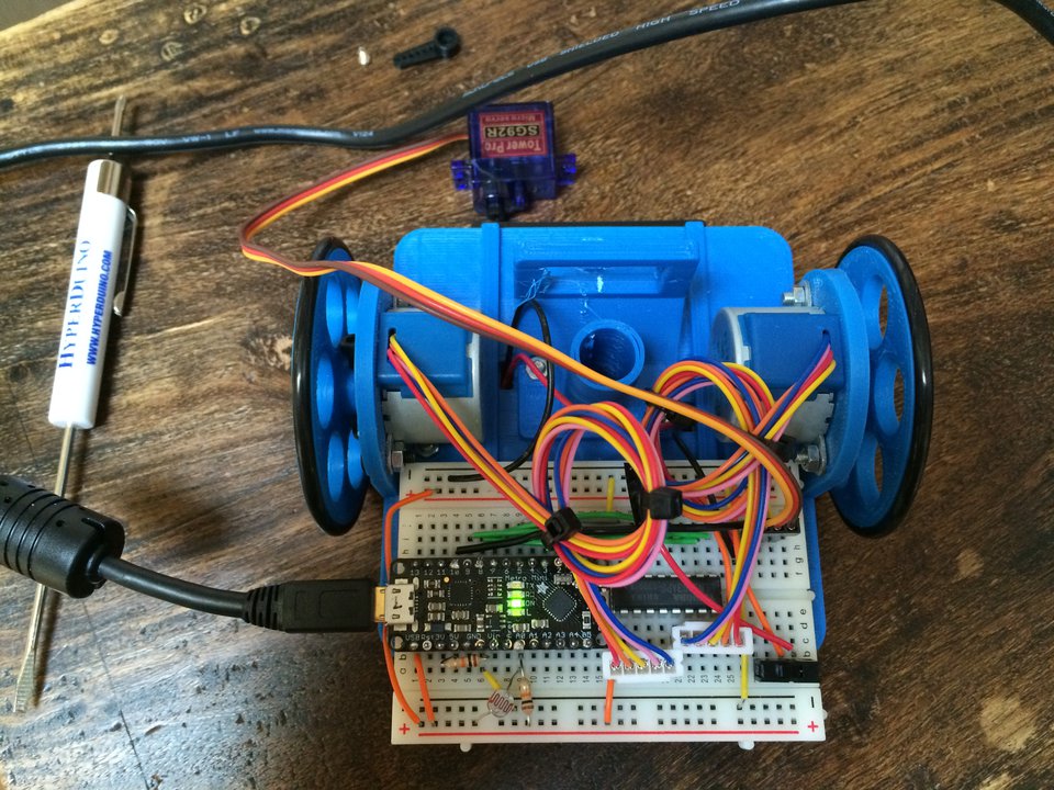
With your turtle oriented as shown
in the image above, plug the black negative lead from the left battery
holder into hole 3 on the rear negative rail. The red positive lead
from that battery holder plugs into hole h26 on the breadboard.
The black negative lead from the
right battery holder plugs into hole g26 on the breadboard. The red
positive lead from that battery holder plugs into hole b30 on the
breadboard.
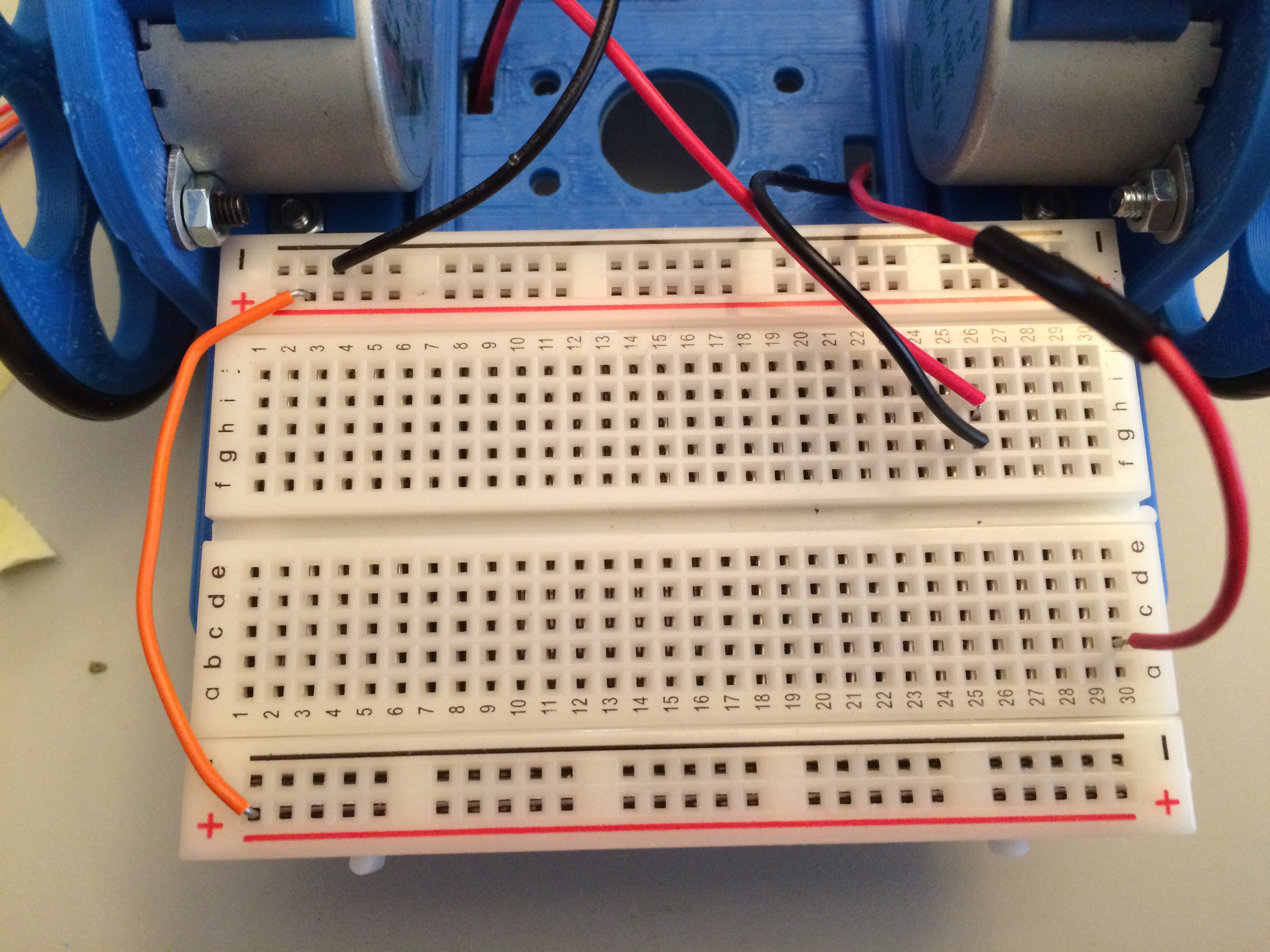
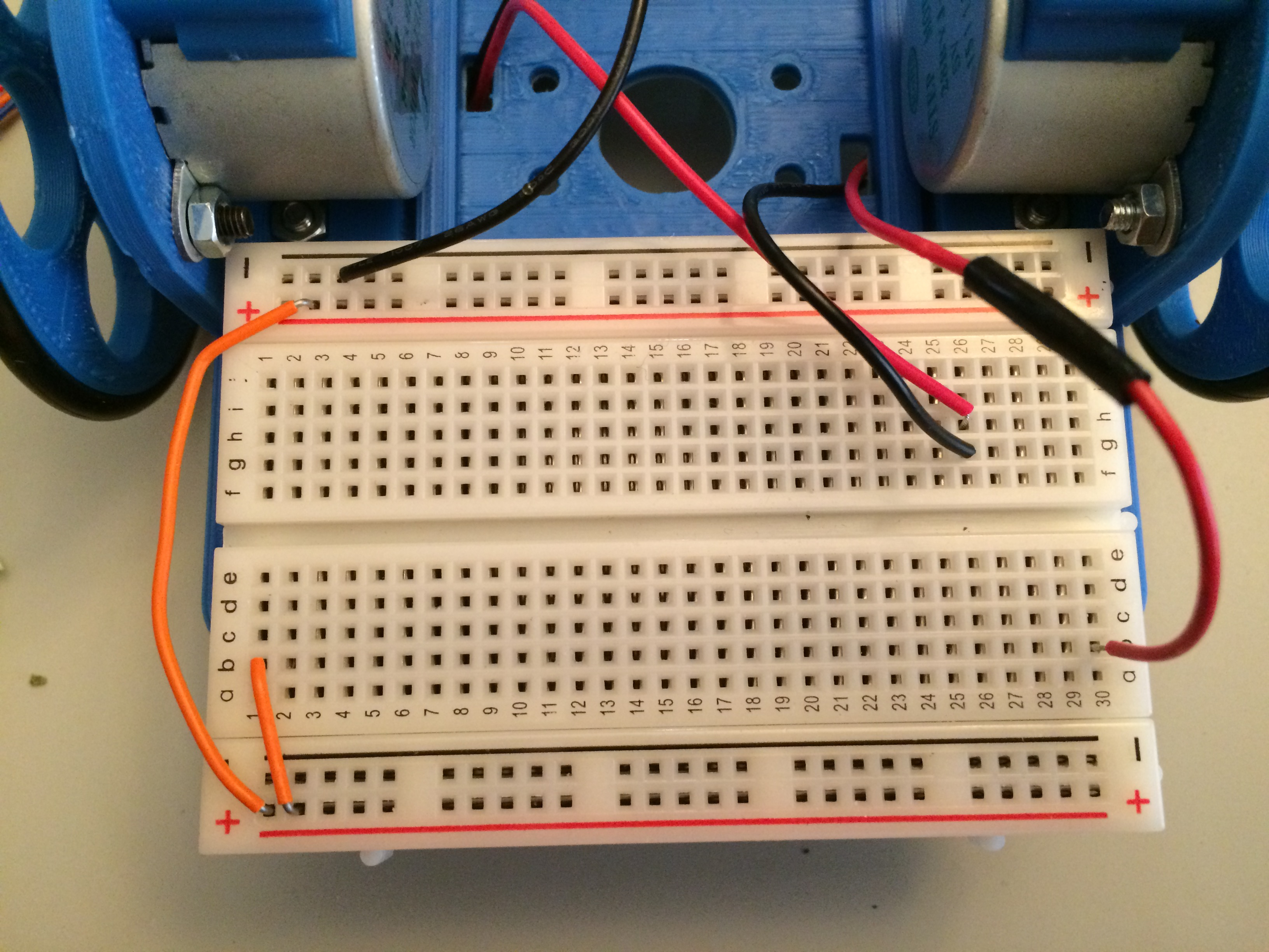
Choose a color of jumper wire to
use for the rest of the positive wiring on the breadboard. I chose
orange.
Connect a jumper wire from the
second hole on the far positive rail to the first hole on the positive
rail closest to you.
Connect a short jumper wire from
the second hole on the close positive rail to hole b1 on the breadboard.
Connect a short jumper wire from
hole 13 on the close positive rail to hole a16 on the breadboard.
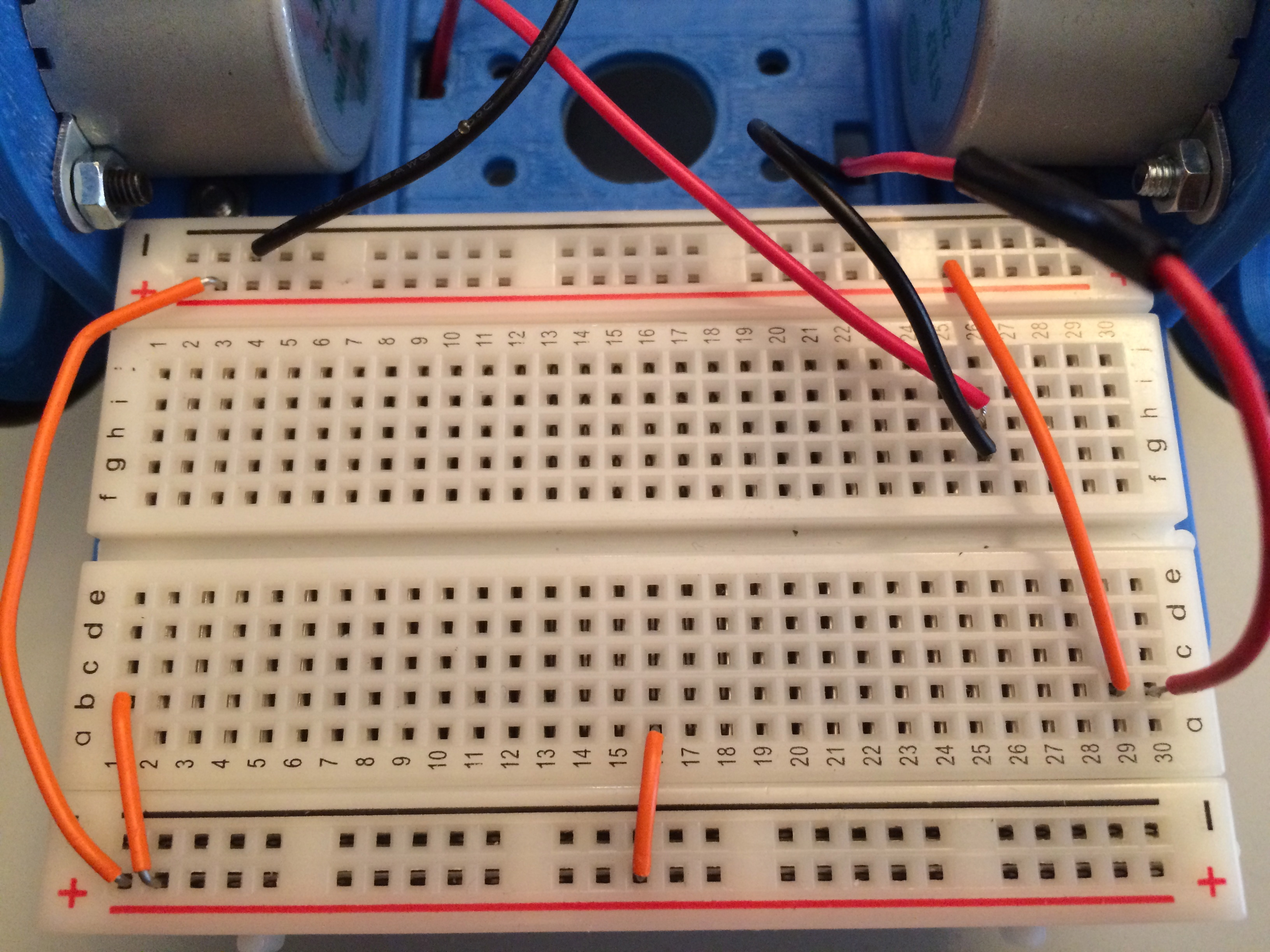
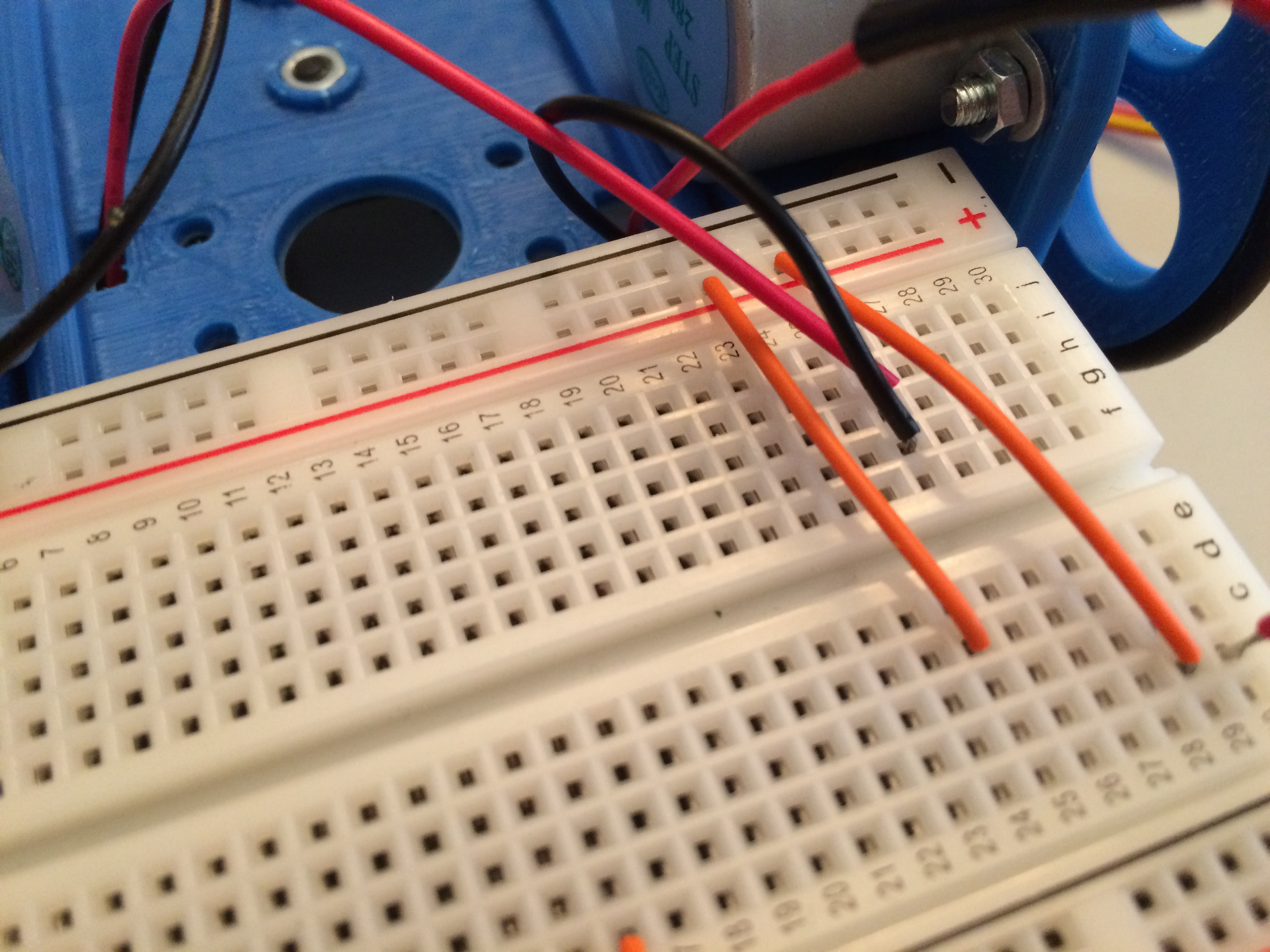
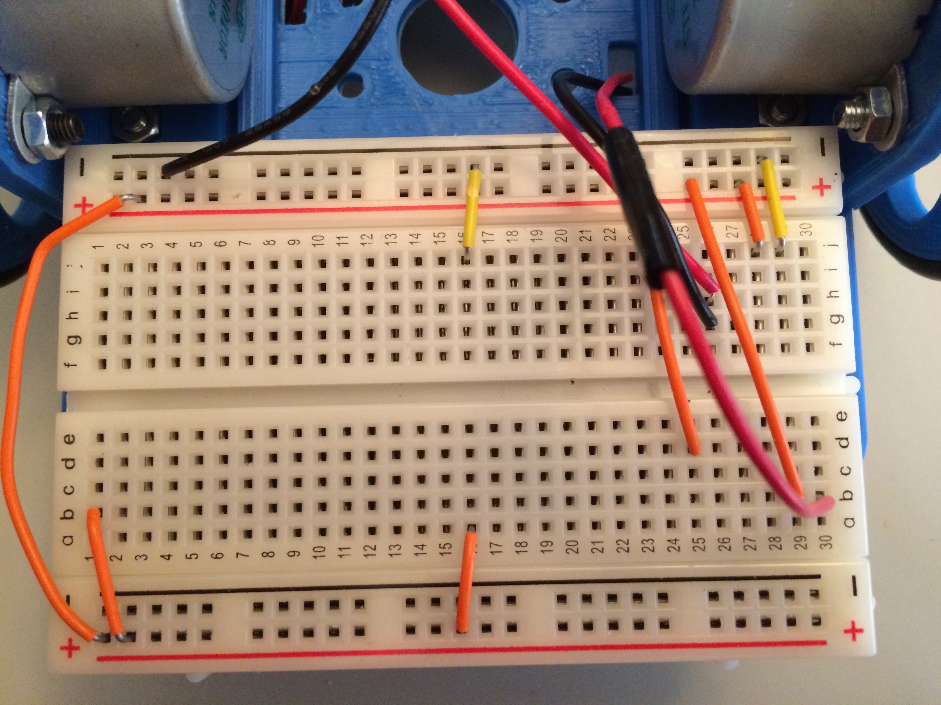
Connect a jumper wire from hole 27
on the far positive rail to hole b29 on the breadboard. (The photo
shows hole 26 on the rail, but the jumper wire should be connected to
hole 27 on the positive rail).
Connect a jumper wire from hole 25
on the far positive rail to hole d25 on the breadboard.
The final positive connection is
from the far positive rail hole 28 to hole j28 on the breadboard.
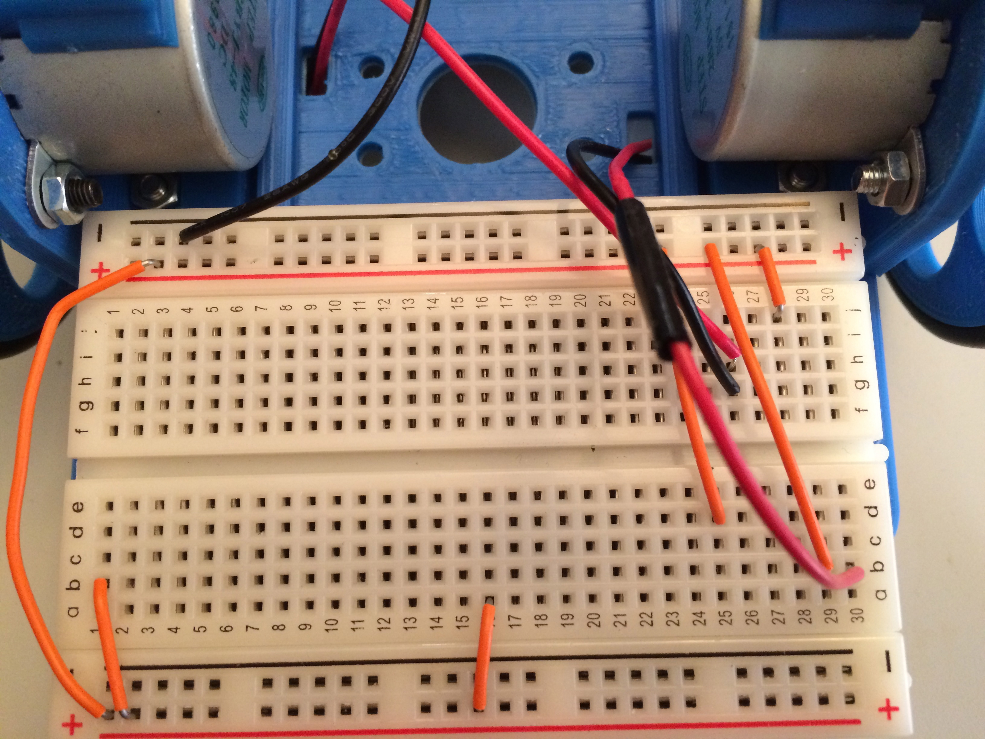
You have now completed the positive
wiring, excluding the power switch.
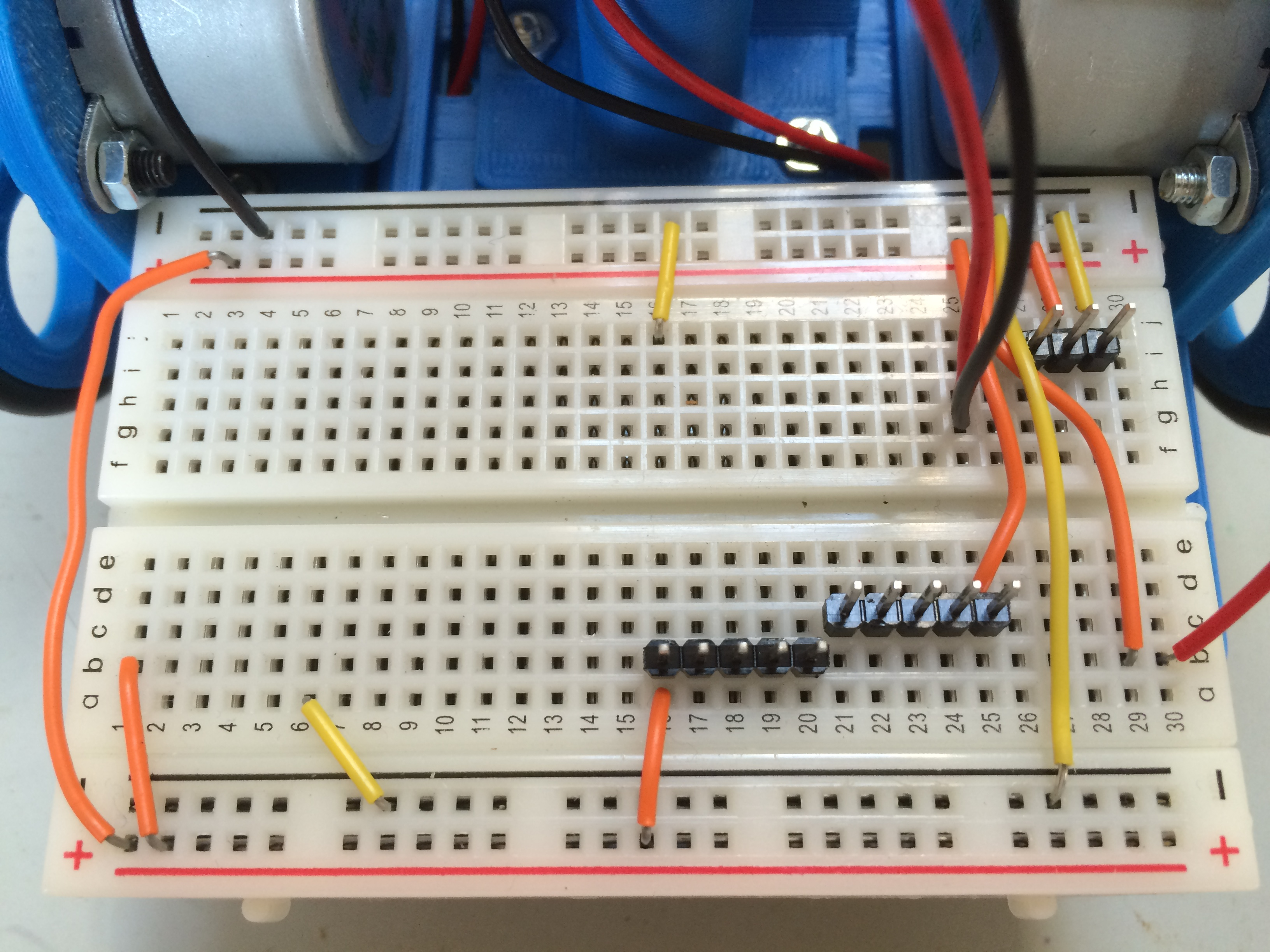
Now you will wire the negative
leads on the breadboard.
Choose a different color jumper
wire for your negative connections. I chose yellow.
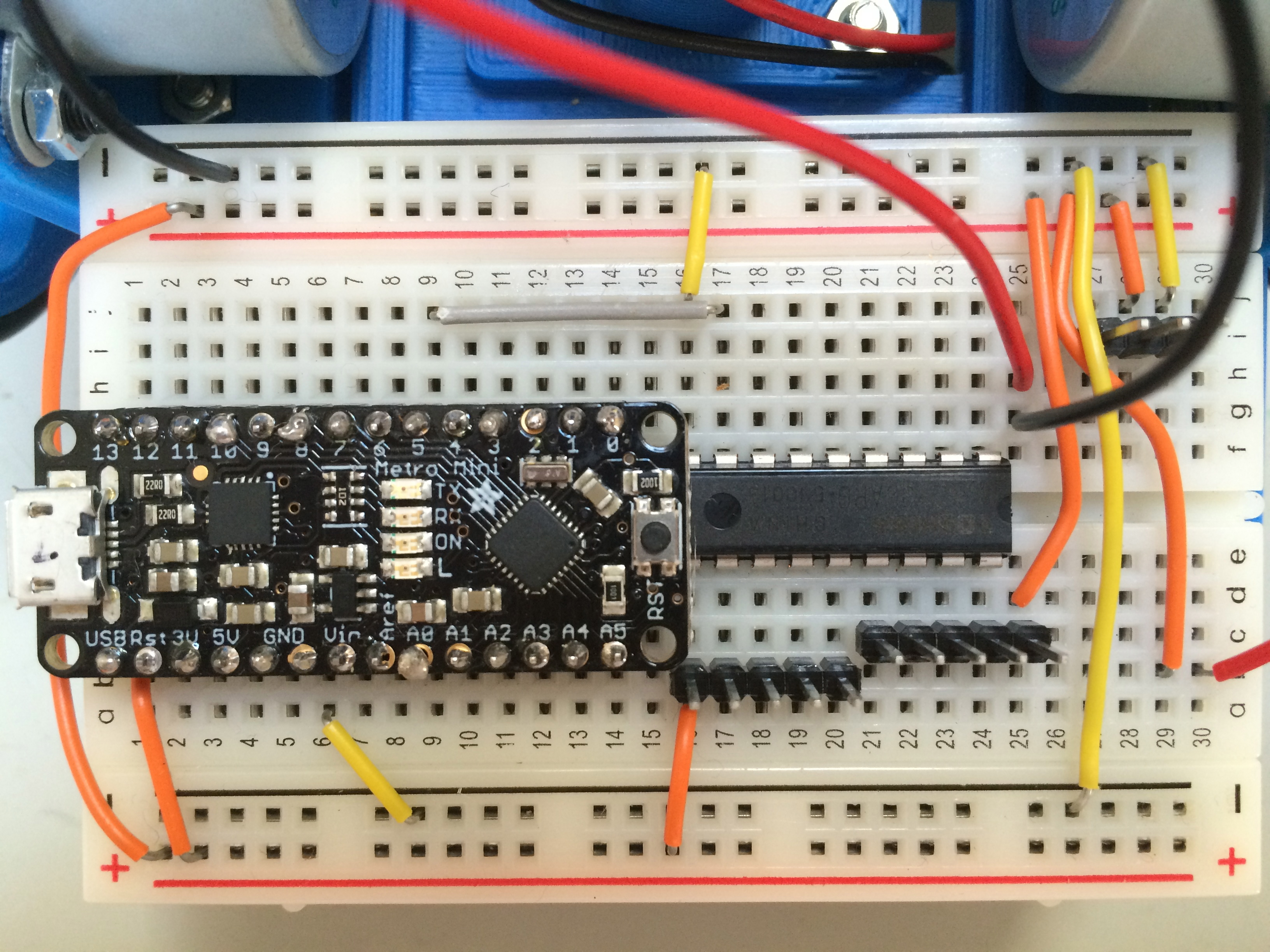
Start with a small jumper wire
between the far negative rail hole 14 to hole j16 on the breadboard.
Next, connect a short jumper wire
from hole 29 on the far negative rail to hole j29 on the breadboard.
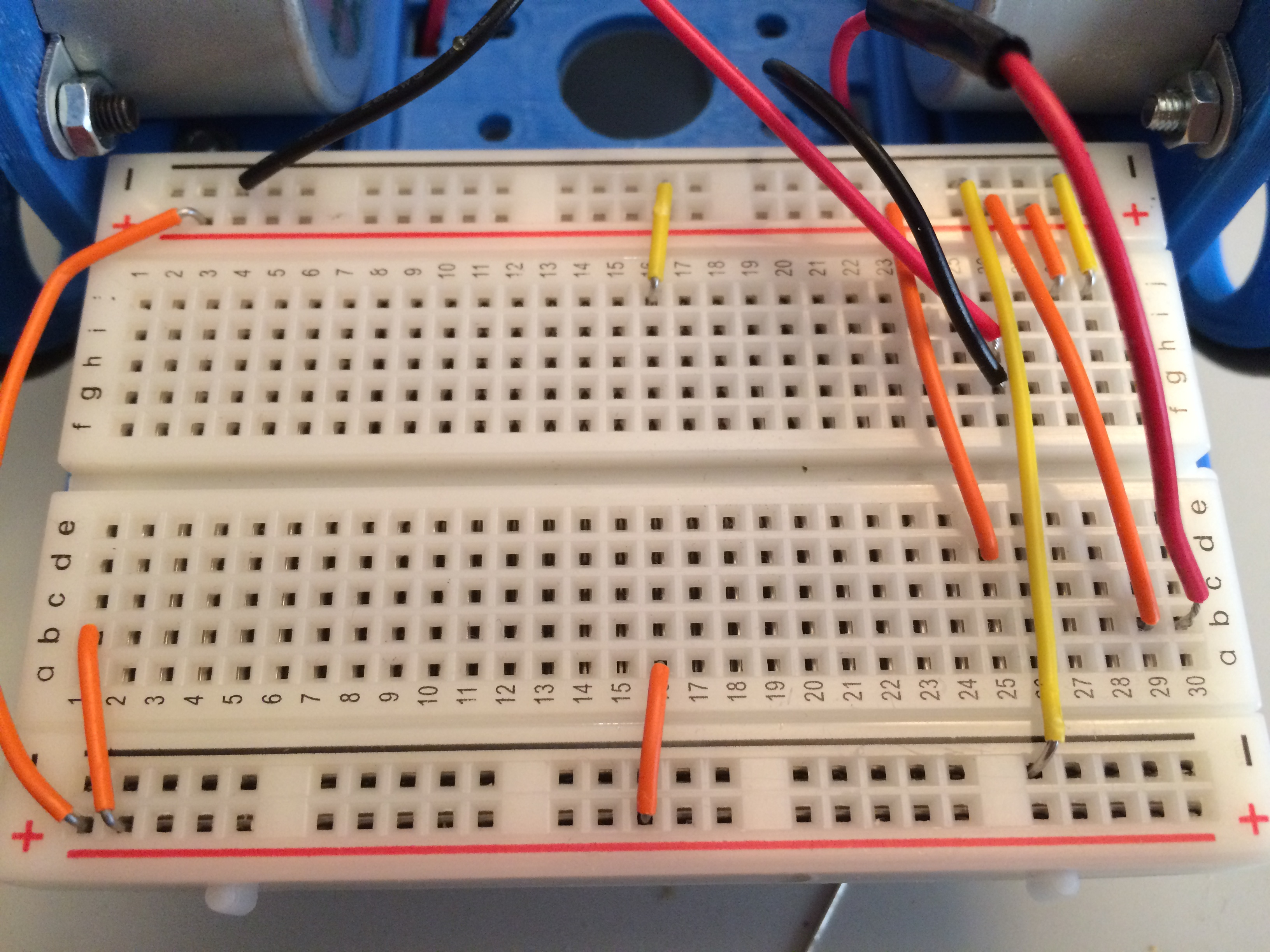
Connect a jumper from the far
negative rail hole 26 to the near negative rail hole 26.
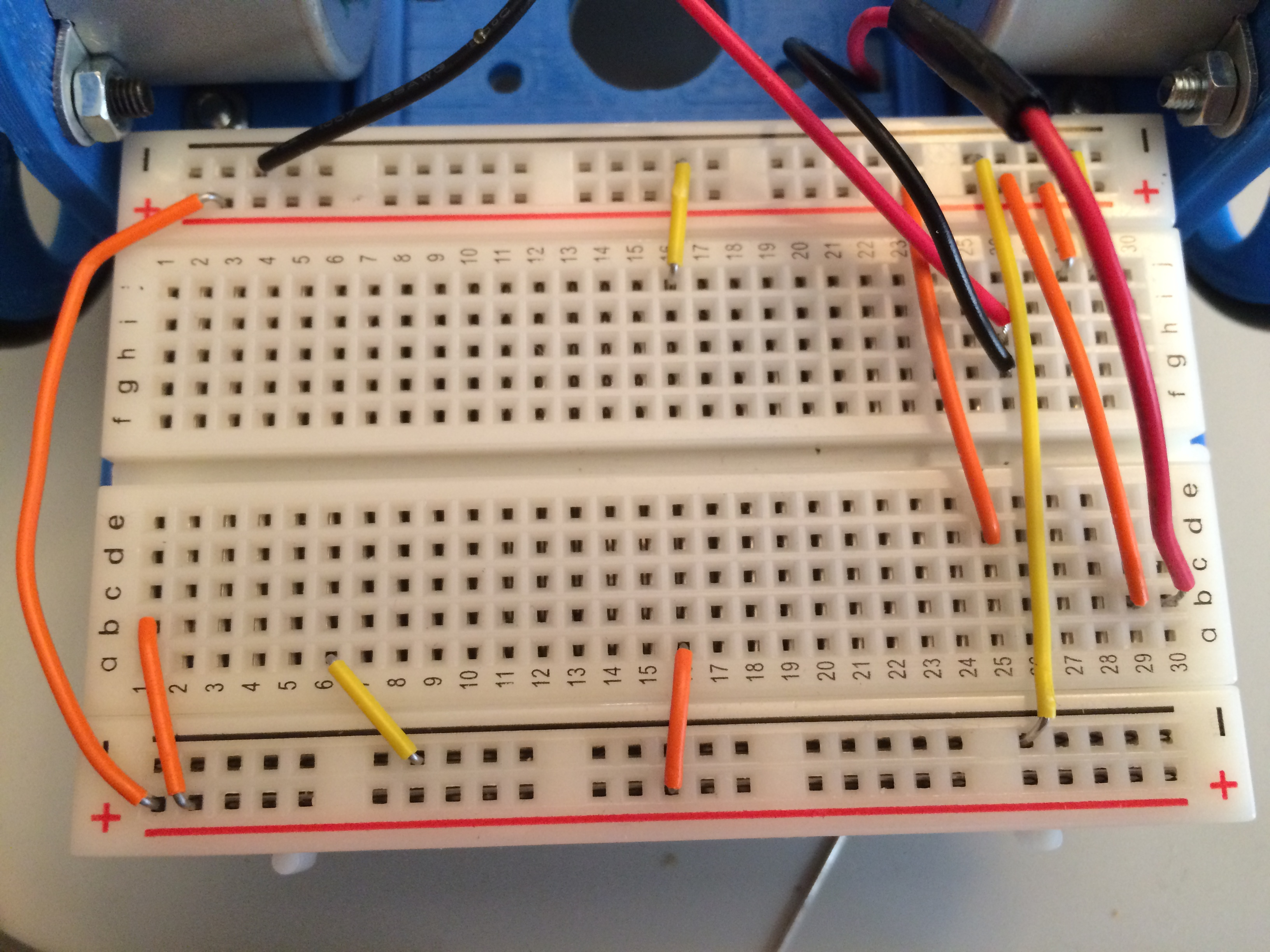
Connect a short jumper from hole 7
on the near negative rail to hole a6 on the breadboard.
Insert header pins into the
breadboard from b16-20 and c21-25.
Insert three header pins in holes
i27-29 on the breadboard.
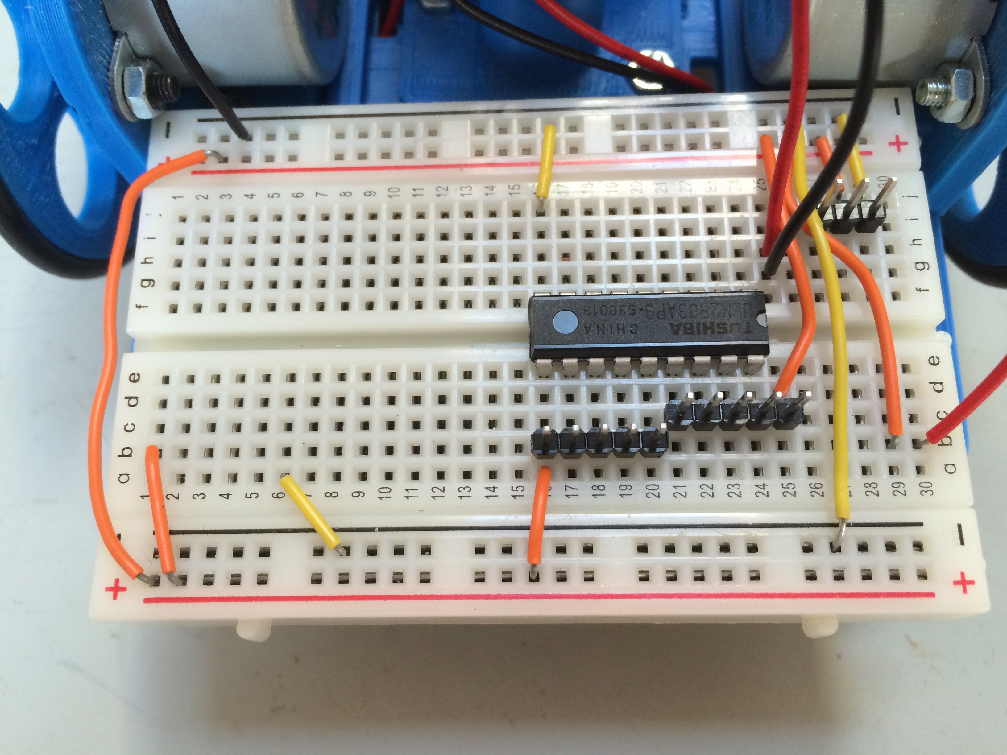
Carefully insert the pins for the
darlington driver, bridging the gap in the breadboard. The notch on the
darlington driver should face the right of the breadboard. The pins go
in holes e16-24 and holes f16-24.
Before you solder the header pins,
load LogoTurtle onto the Metro Mini.
Install the FTDI VCP drivers as well as the SiLabs CP210x drivers from SiLabs.
Download the latest version of LogoTurtle.
Connect the Metro Mini to the Mini
USB cable. Connect the USB cable to your Mac or PC.
Open the Assembler.jar in the
logovm folder.
Click the ASM button. The console
will report back a number of words.
Click Download. The console will
report how long it took and produce a string of hexadecimal numbers and
letters.
Success should report written in 1 second with the hex string: 0000 - 940C 0034 940C 3F00 940C 3F00 940C 3F00.
Failure takes 8 seconds and the hex string will be something like: 0000 – FFFF FFFF FFFF FFFF FFFF FFFF FFFF FFFF.
Quit the Assembler.
Open Logo.jar in the logo folder.
Click the Download button. After
the console reports Downloaded, type the following in the console (the italics are what LogoTurtle should respond):
print 42
42
print 4 + 5
9
Quit Logo.jar.
Unplug the Metro Mini from the USB
cable.
Solder the header pins to the Metro
Mini.
Carefully insert the header pins
from the Metro Mini, bridging the gap in the breadboard. The pins
closest to the front of the breadboard start in hole c1 and continue to
c14. The pins on the far end of the breadboard start in hole g1 and
continue to g14.
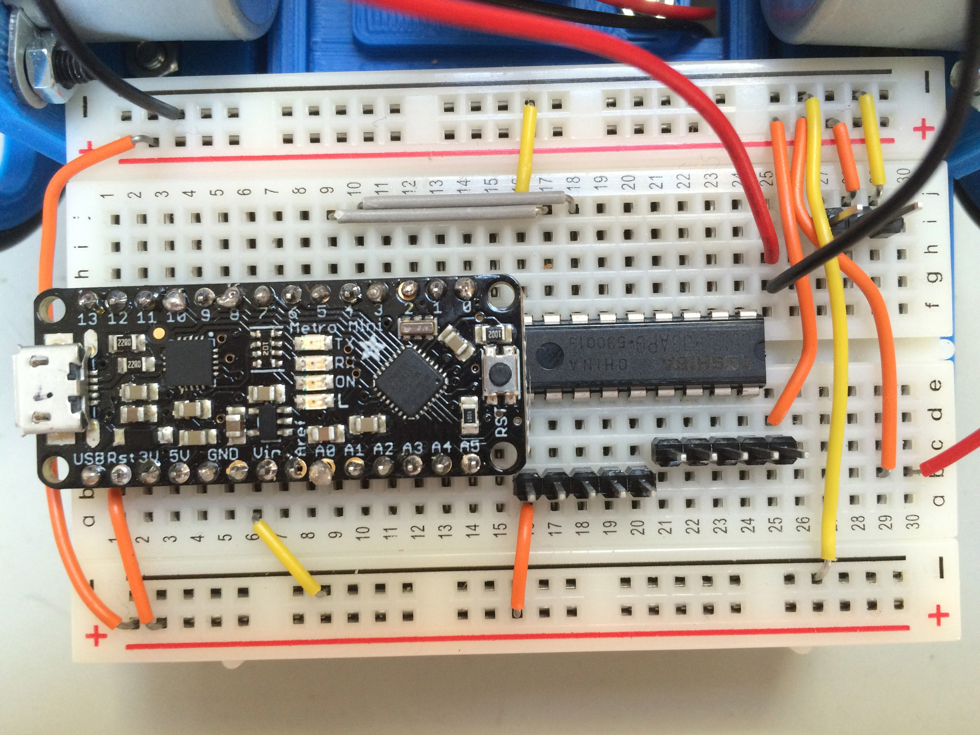
Choose one color jumper wire for
the left stepper motor wiring. I chose gray.
Connect a jumper wire from hole j9
on the breadboard to hole j17. This connects pin 5 on the Metro Mini to
pin 8 on the darlington driver.
Connect a jumper wire from hole j10
on the breadboard to hole j18. This connects pin 4 on the Metro Mini to
pin 7 on the darlington driver.
Connect a jumper wire from hole i11
on the breadboard to hole i19. This connects pin 3 on the Metro Mini to
pin 6 on the darlington driver.
Connect a jumper wire from hole i12
on the breadboard to hole i20. This connects pin 2 on the Metro Mini to
pin 5 on the darlington driver.
You have completed wiring the left
stepper motor array.
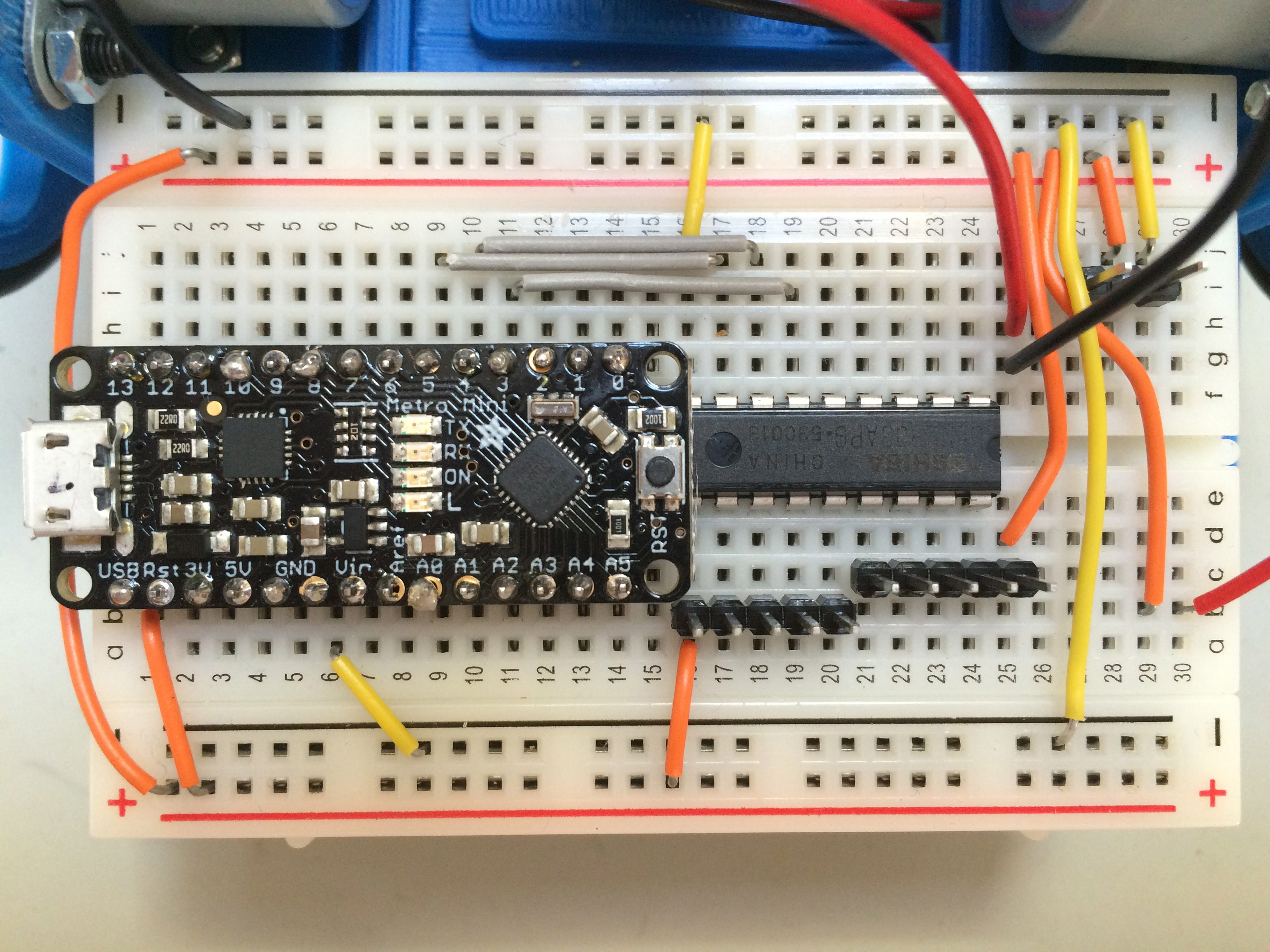
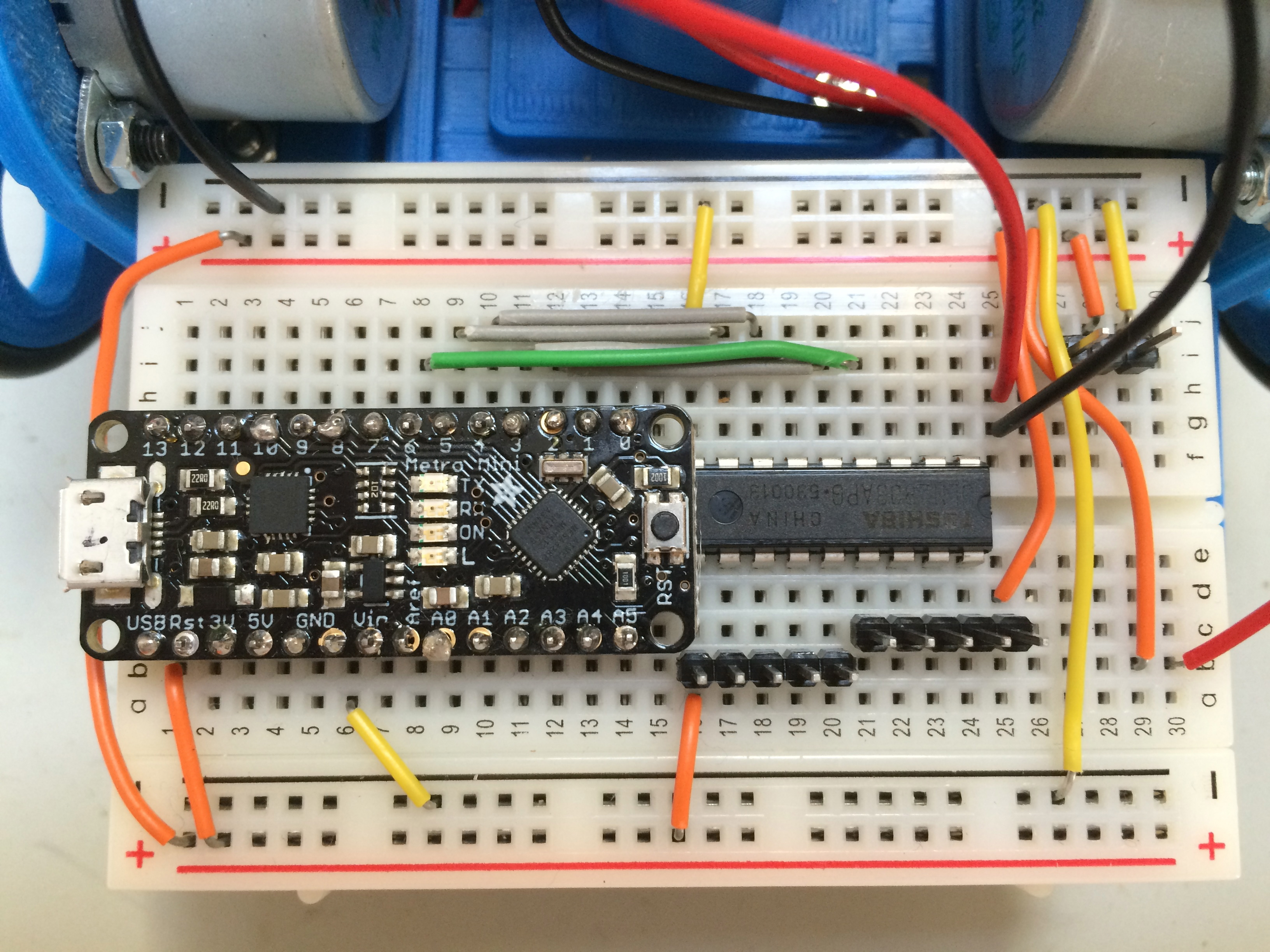
Choose a different color jumper
wire for the right stepper motor wiring. I chose green.
Connect a jumper wire from hole i8
on the breadboard to hole i21. This connects pin 6 on the Metro Mini to
pin 4 on the darlington driver.
Connect a jumper wire from hole i7
on the breadboard to hole i22. This connects pin 7 on the Metro Mini to
pin 3 on the darlington driver.
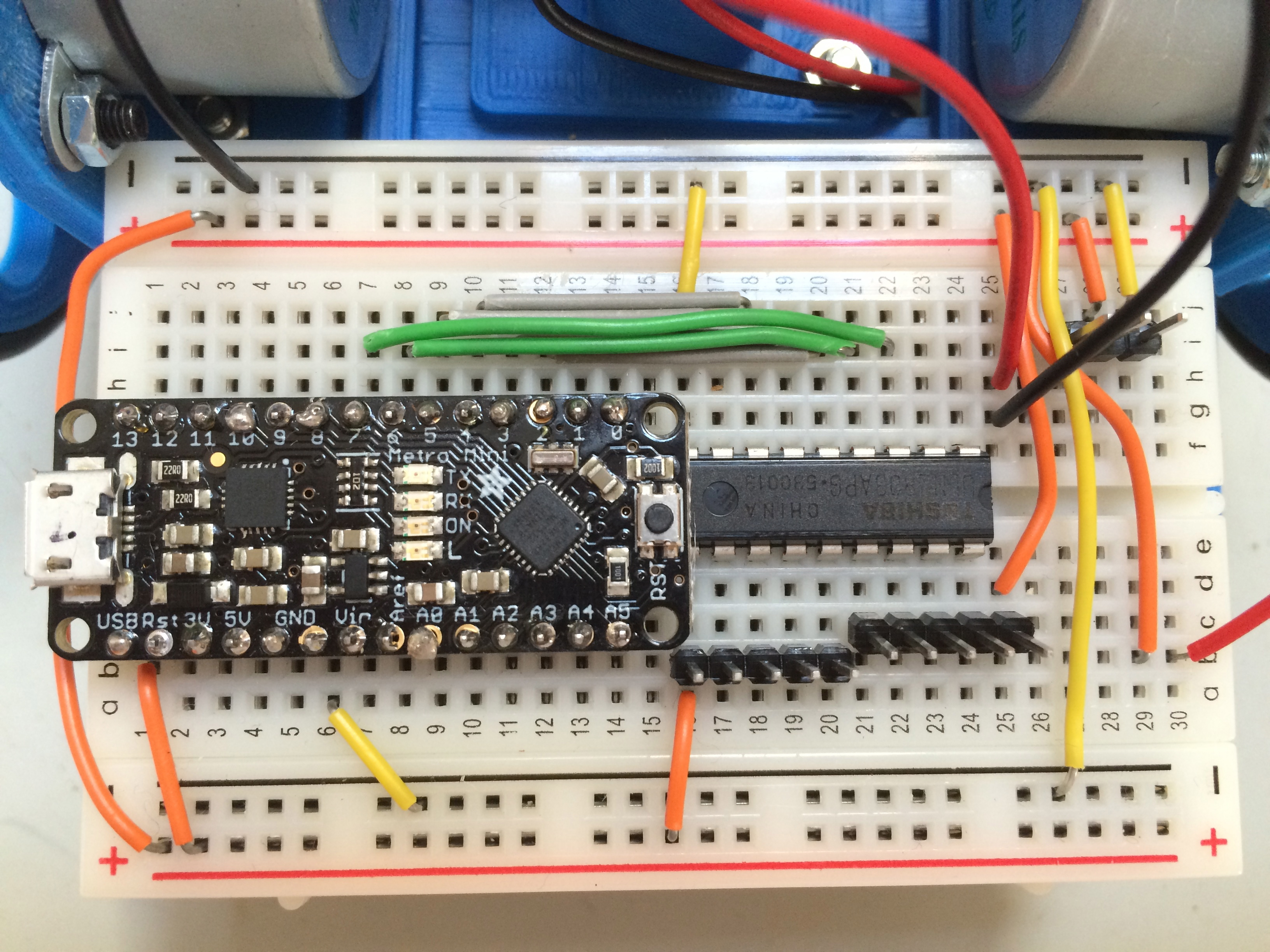
Connect a jumper wire from hole j6
on the breadboard to hole j23. This connects pin 8 on the Metro Mini to
pin 2 on the darlington driver.
Connect a jumper wire from hole j5
on the breadboard to hole j24. This connects pin 9 on the Metro Mini to
pin 1 on the darlington driver.
You have completed wiring the left
stepper motor array.
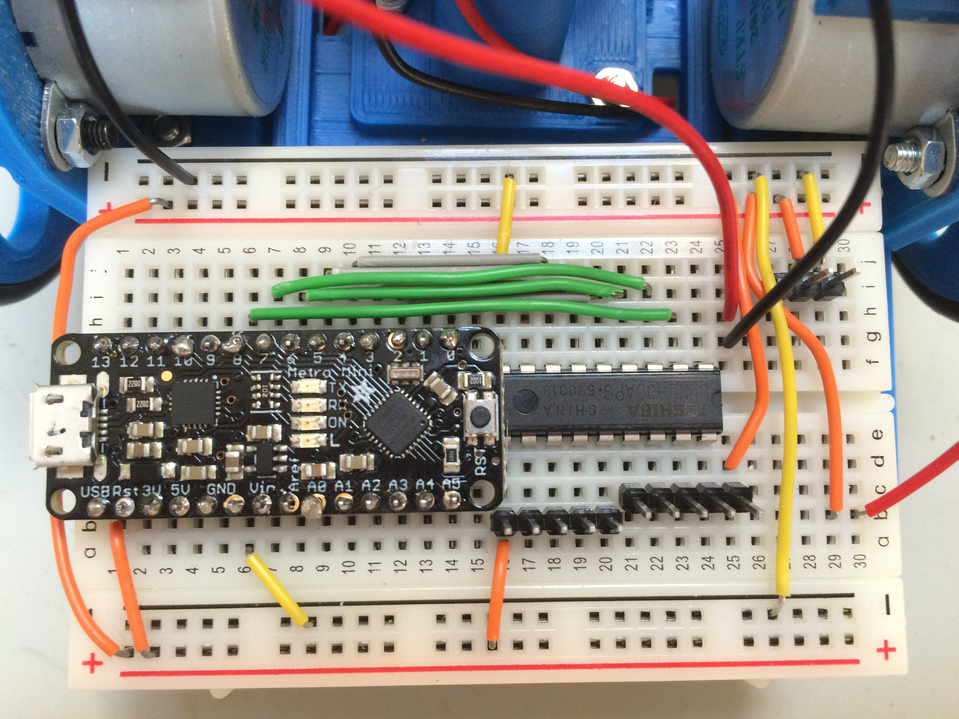
Connect a jumper wire from hole h4
to hole j27. This connects pin 10 on the Metro Mini to the servo array.
Connect the wires from the left
stepper motor to the left header pins on the breadboard. Make sure the
red wire matches the jumper wire on hole a16. Connect the wires from
the right stepper motor to the right header pins on the breadboard. Make sure the red wire on the stepper
motor matches the jumper wire from the far positive rail to hole d25.
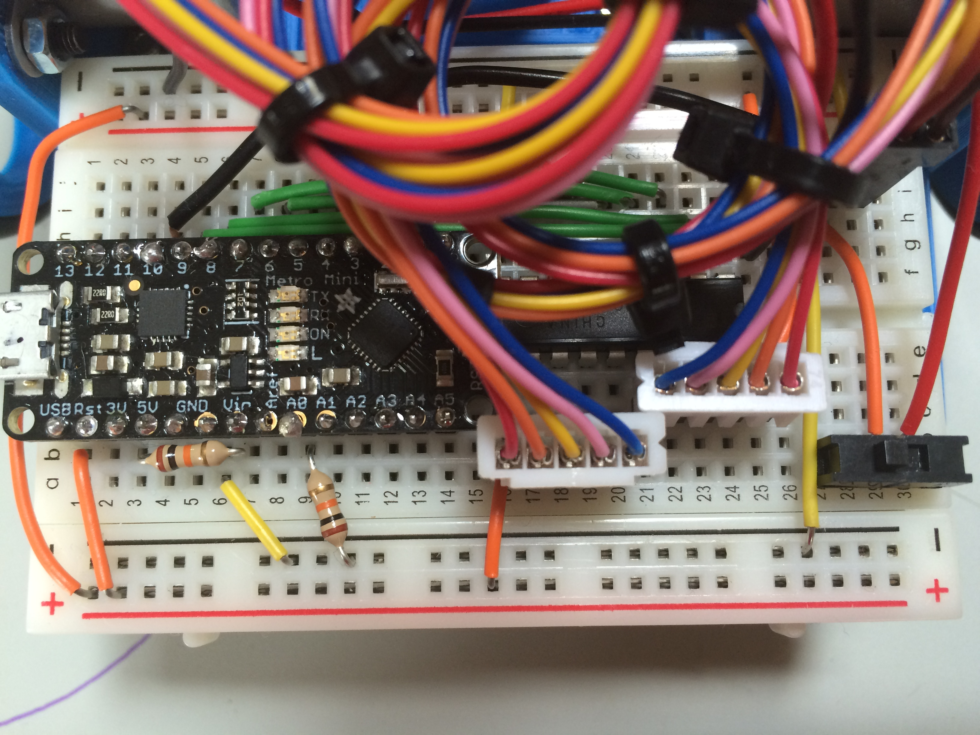
Insert the leads from a 10k
resistor in holes b4 and b6 on the breadboard.
The power stays "on" for some time
after you pull the USB plug. When the power to the Metro Mini gets
restored it looks to the Arduino more like a reset than a power up. By
adding a 10k resistor between the 5V pin of the Arduino and GND,
residual power is drained from the Metro Mini.
Insert a 10k resistor from hole 8
on the near negative rail to hole b9 on the breadboard.
Insert one lead of the photo cell
into hole 5 of the near positive rail. Insert the other lead into hole
a9 on the breadboard.
Insert the SPDT power switch into
holes a28-30 on the breadboard.
Reattach the 3D printed pen
tube/servo bracket.
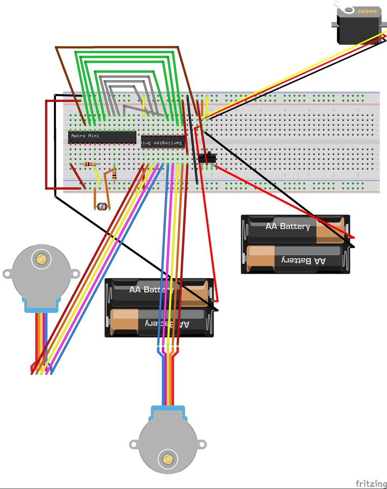
Using the Fritzing diagram below to
double-check all your wiring.
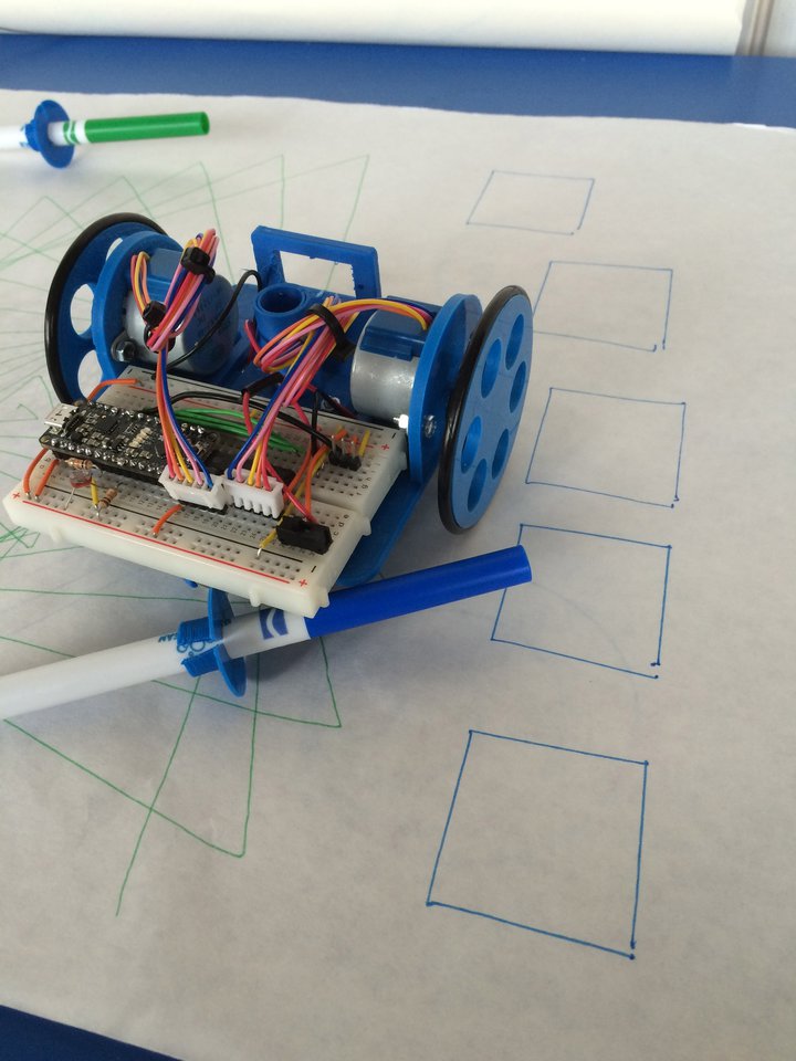
Congratulations! Your LogoTurtle is
constructed!
Next you will calibrate the turtle
to make sure it is working properly.
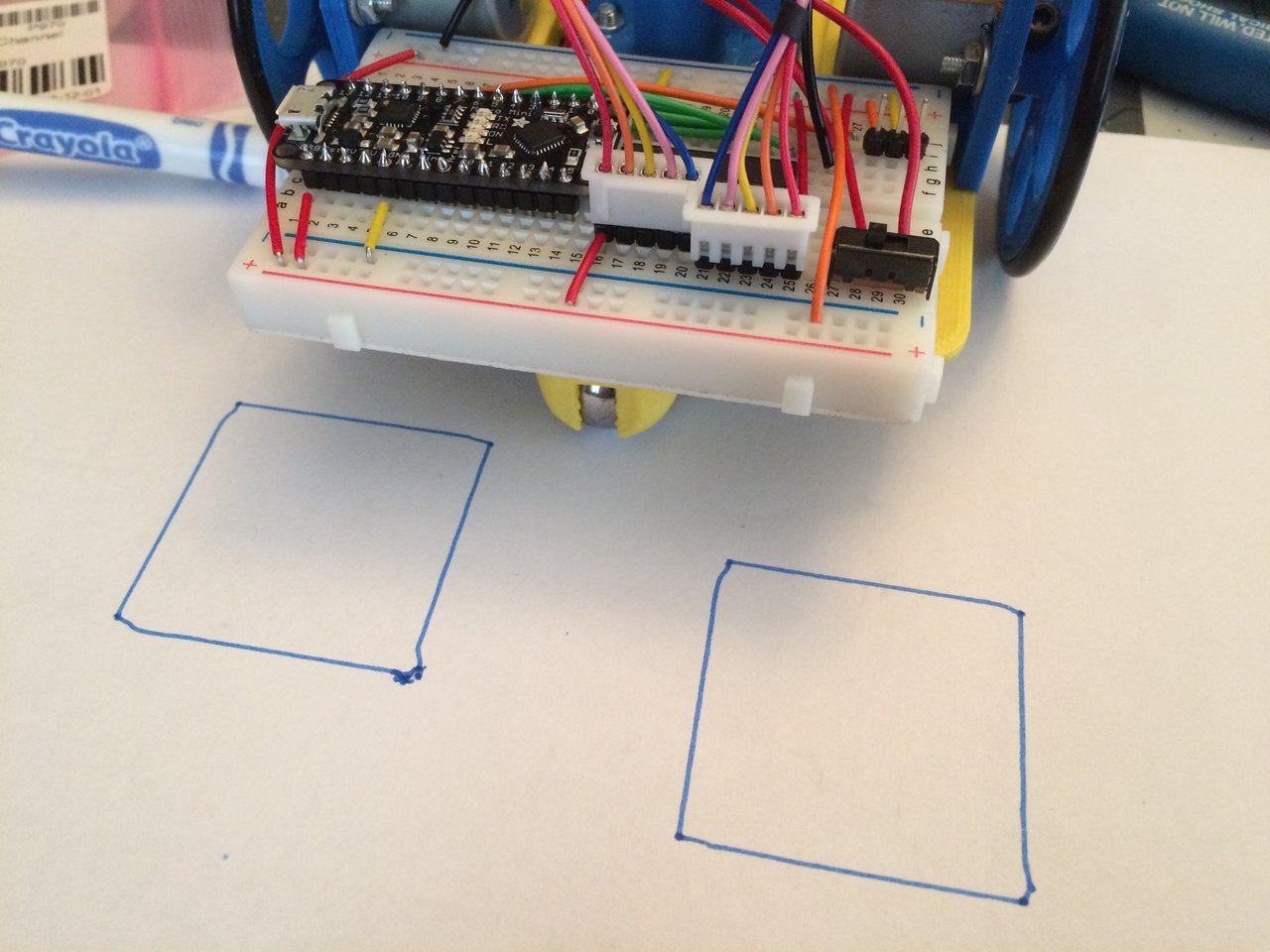
Place a pen in the 3D printed pen
collar. Make sure the the pen is in contact with the paper below the
turtle.
Switch the power switch on.
Press the reset button on the Metro
Mini. The turtle will draw a square. It should have angles close to 90
degrees and the lines should meet.
If the square is skewed or not
quite square, adjust the wheel base by moving the wheels in or out on
the stepper motors. Set on a ruler, a well-calibrated turtle should
have a wheel base of 112mm. Use a heat gun to warm the wheel hub if it
is too snug to fit on the stepper motor.
If the turtle appears not to be
making full 90 degree turns, you might need to place a shim between the
stepper motors. This turtle needed its steppers to be spread slightly
to get the square nearly perfect.
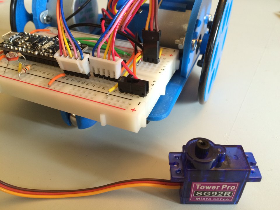
Next, you will add the servo to the
floor turtle so it is able to raise and lower the pen.
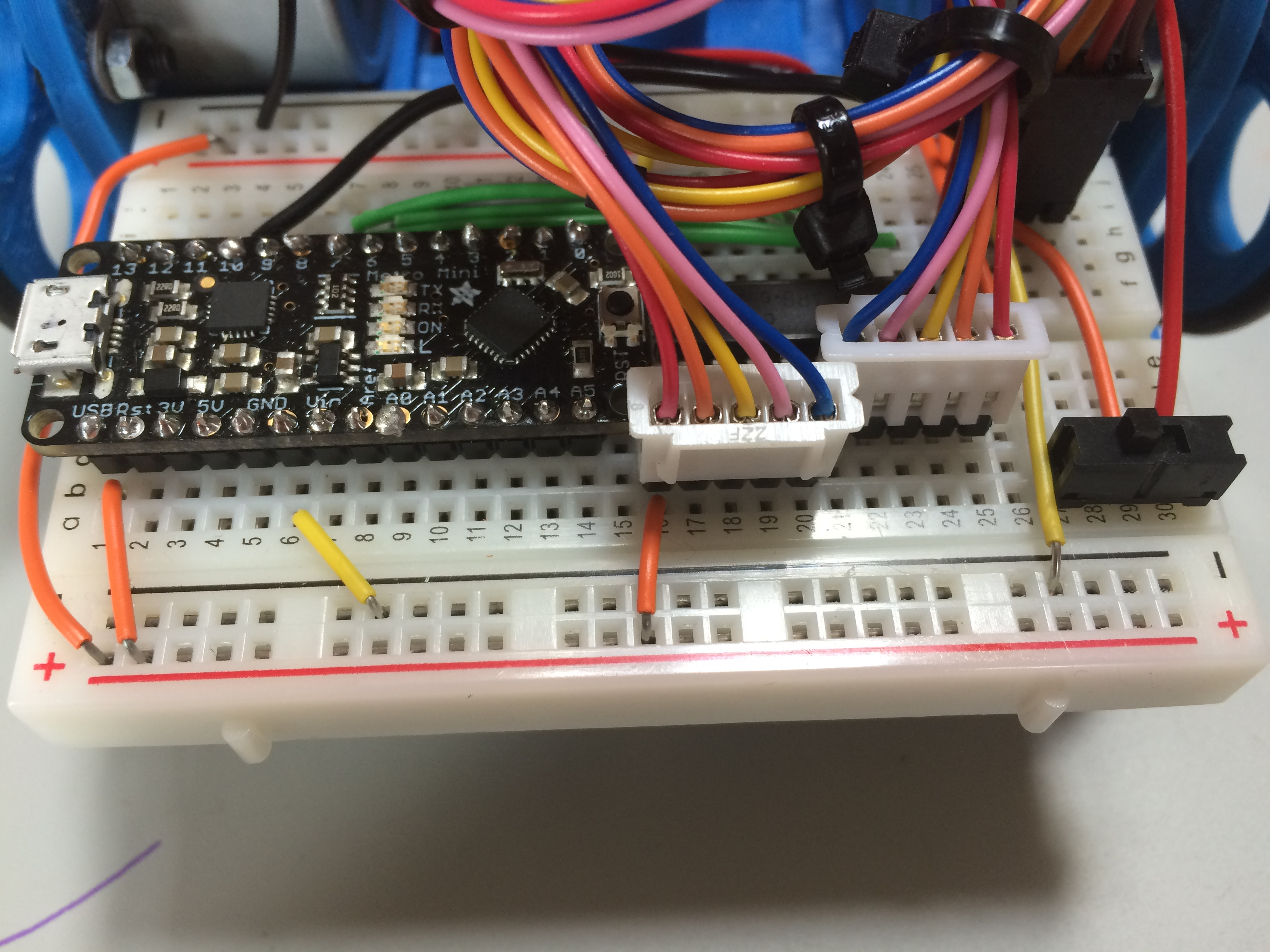
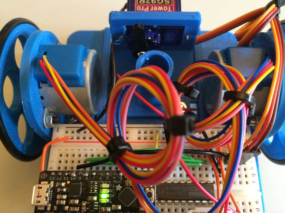
Plug the servo into the three
header pins on the breadboard. Be very careful about connecting the
correct pins to the correct servo wires. The rightmost wire on the
breadboard is negative, and the corresponding wire on the servo is
brown colored.
Plug the turtle into the USB cable,
plug the USB cable into the computer, and open Logo.jar. The servo will
move to the down position.
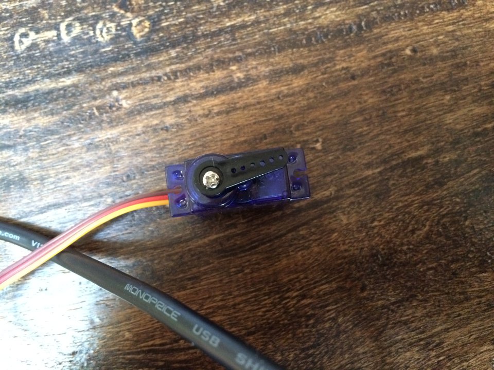
Use the small screw that comes with
the servo to attach the horn to the servo. Mind you do not turn the
servo while you attach the horn.
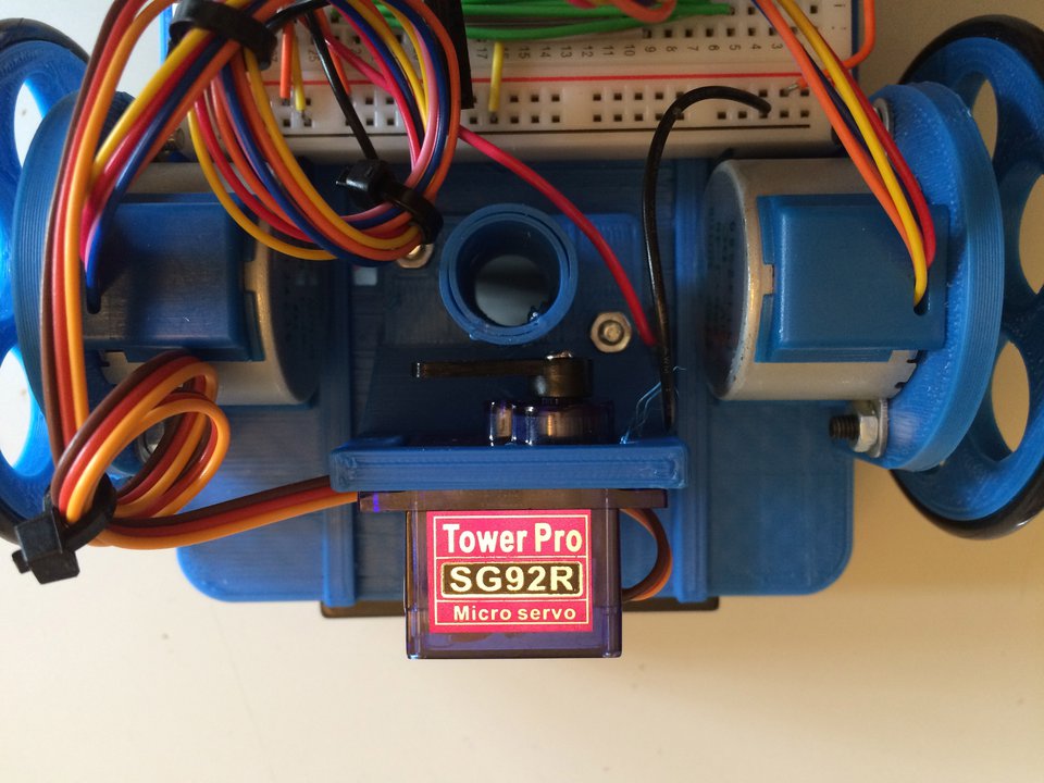
Snip the support in the middle of
the bracket to remove it. Install the servo in the bracket with two
screws. Make sure the wires come out of the right side of the servo
when it is installed.
Power on the turtle. The servo will
move to the up position.
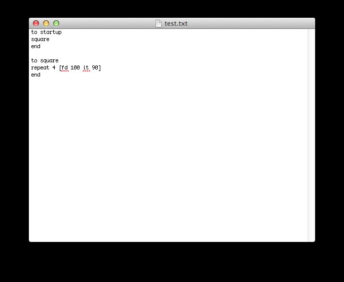
Open the test.txt file in the logo directory with a text
editor.
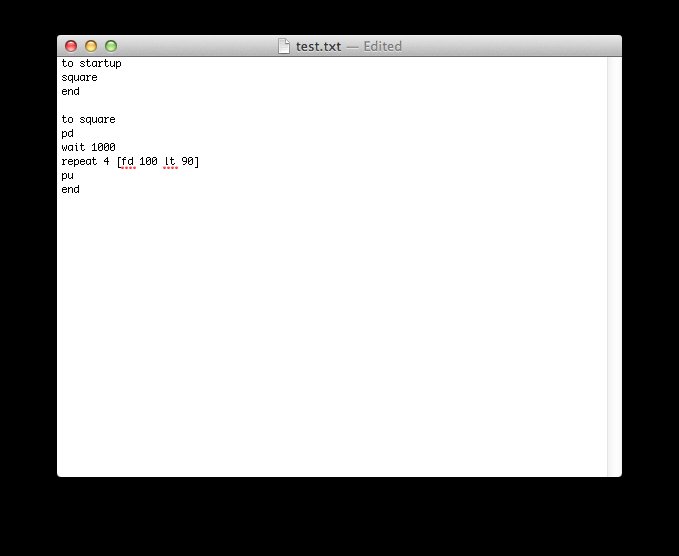
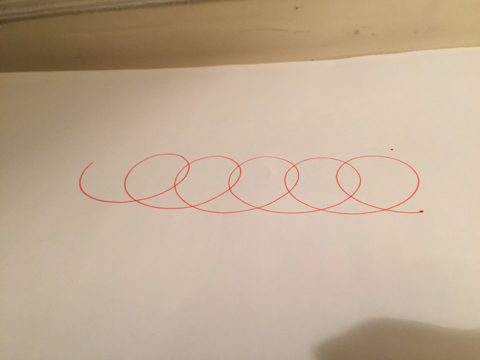
Add pen commands to the square
procedure. It is a good idea to ask the turtle to wait 1000 after
putting down the pen to make sure the pen is on the paper before the
turtle begins moving.
Connect the turtle to the USB
cable. Click the download button in logo to transfer the updated square
routine.
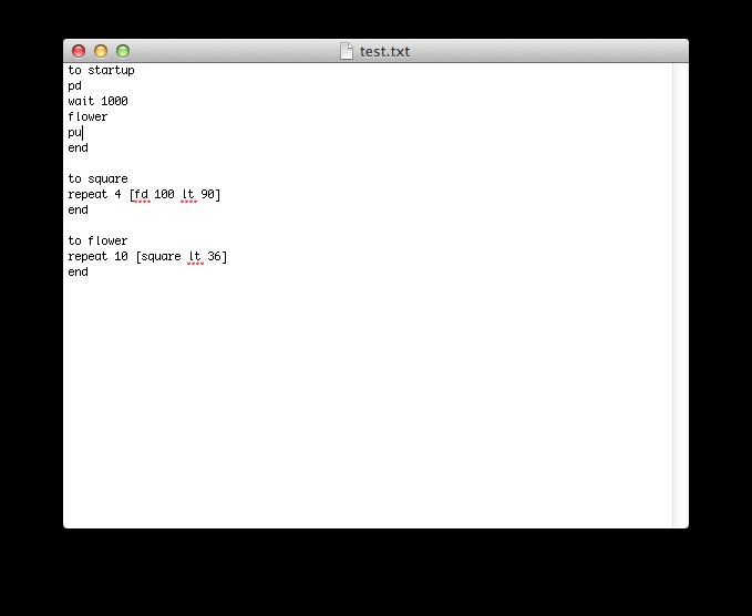
Remix the square procedure and move
the pen commands to the startup procedure. The startup procedure is run
when the reset button is pressed on the Metro Mini.
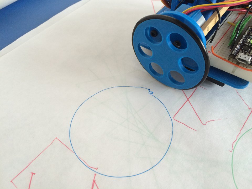
Experiment with the arclt and arcrt commands. The syntax is arclt angle radius. This turtle drew arclt 360 100.
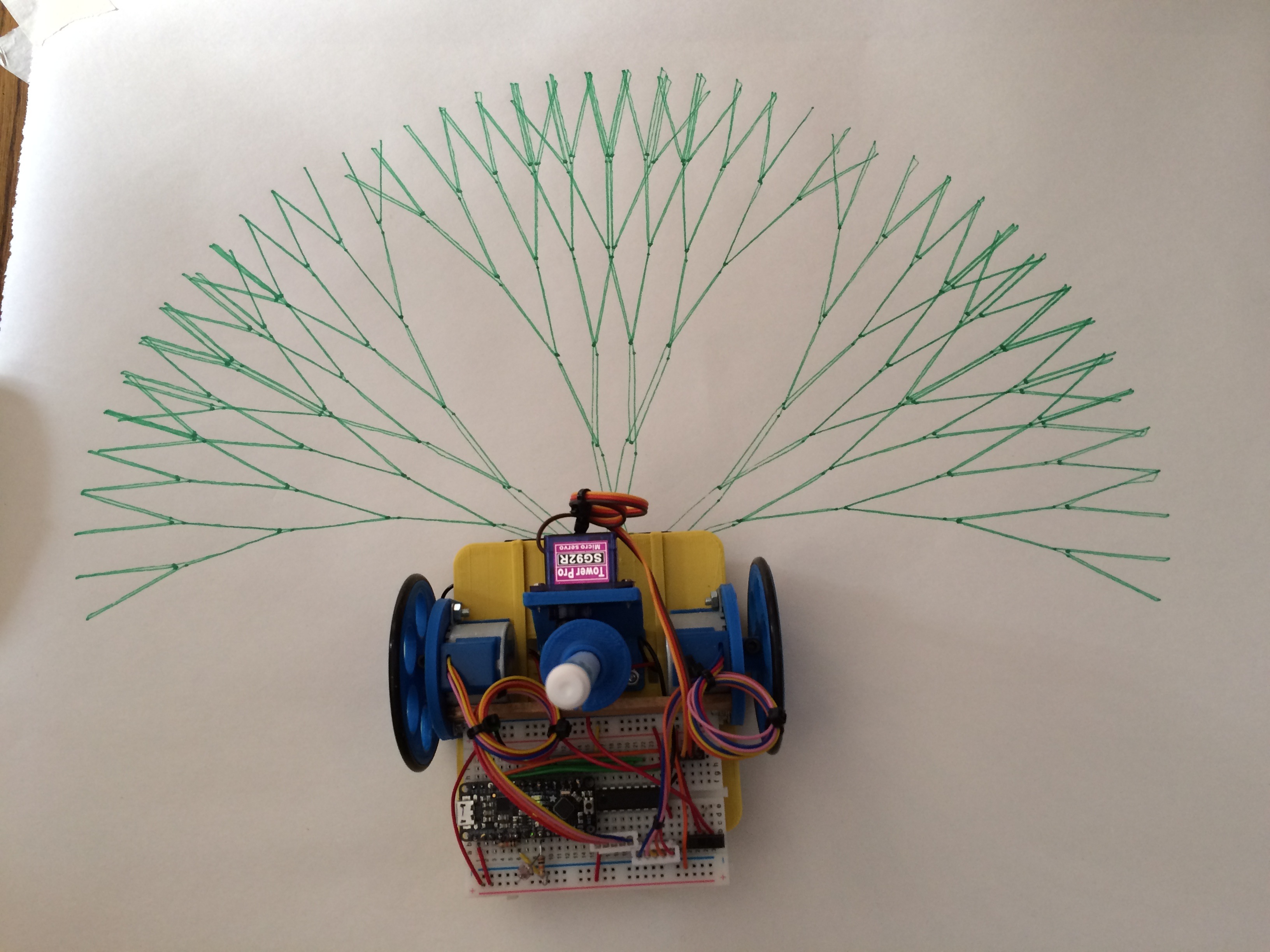
You can take readings from the
photocell sensor. The photocell is plugged into A0 on the Metro Mini,
so print
a0 or repeat 100 [print a0
wait 100] can be interesting
starting points.
to startup
pd wait 1000
let [n a0]
repeat 200 [
arcrt 10 :n
make "n a0
]
pu
alloff
end
Troubleshooting
Double-check all your wiring
against the circuit diagram above.
If LogoTurtle fails to load on the
Metro Mini, load the example Blink sketch from Arduino to confirm your
computer is communicating properly with the Metro Mini.
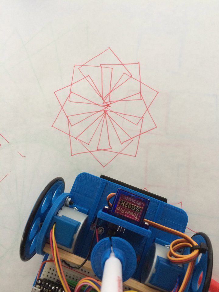
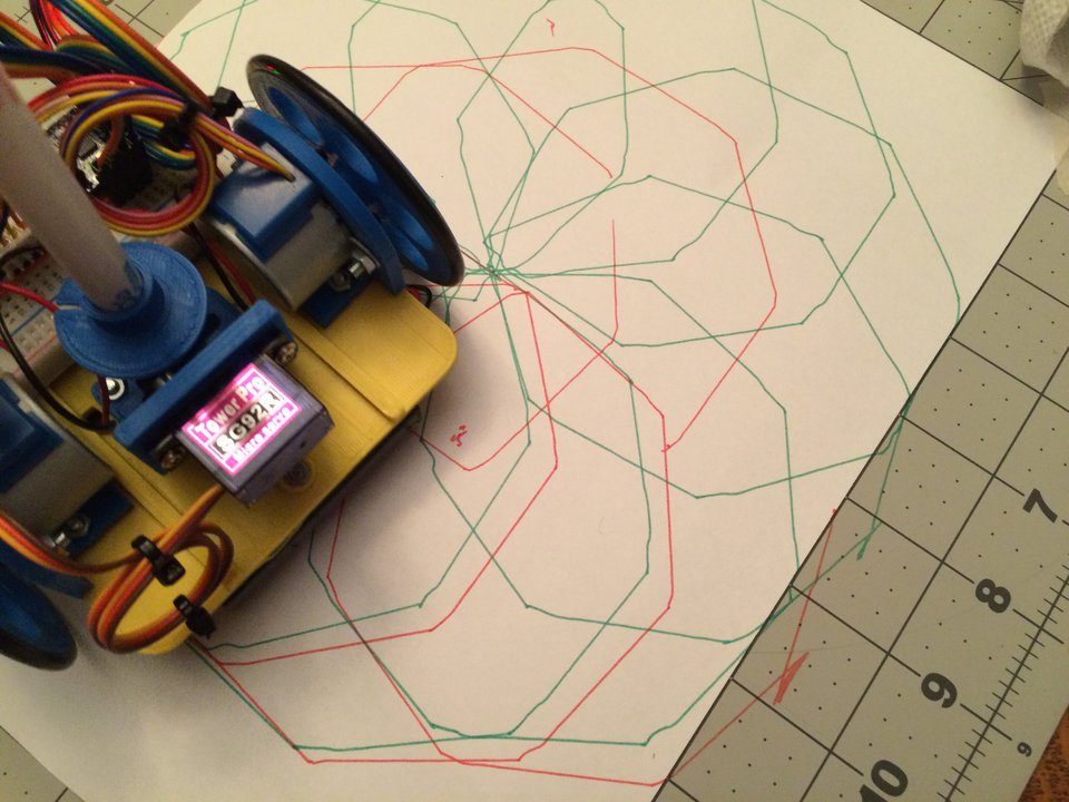
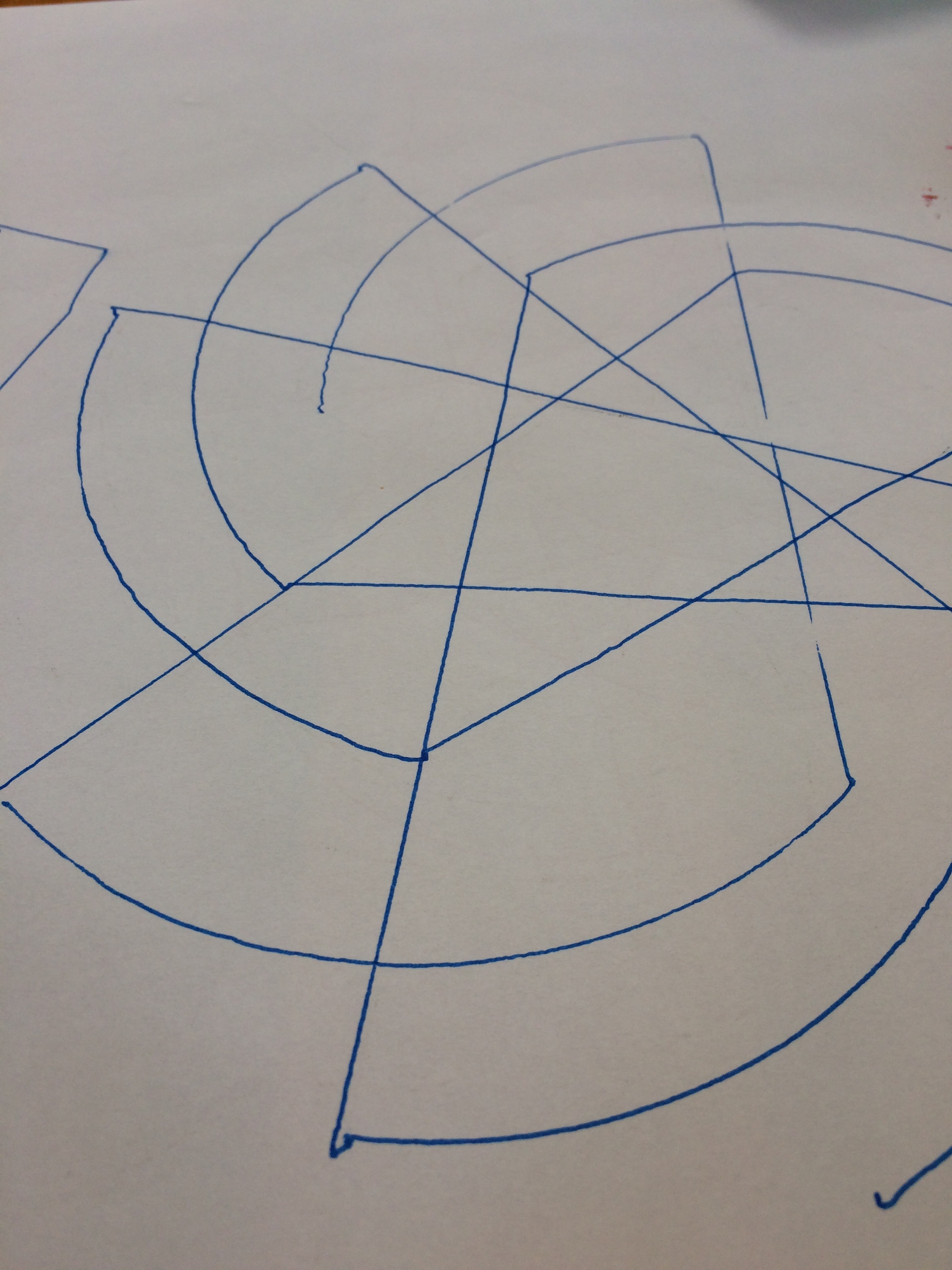
Make sure that when the servo is in the down position that the pen
holder rests flush on the robot's pen holder. If the pen holder on the
pen is not in contact with the robot the lines will have weird backlash
as the robot changes direction and the lines will not look beautifully
crisp. The green lines in the example below were drawn without contact
with the robot, the red with contact. Notice the line segments after
the 45� turns.
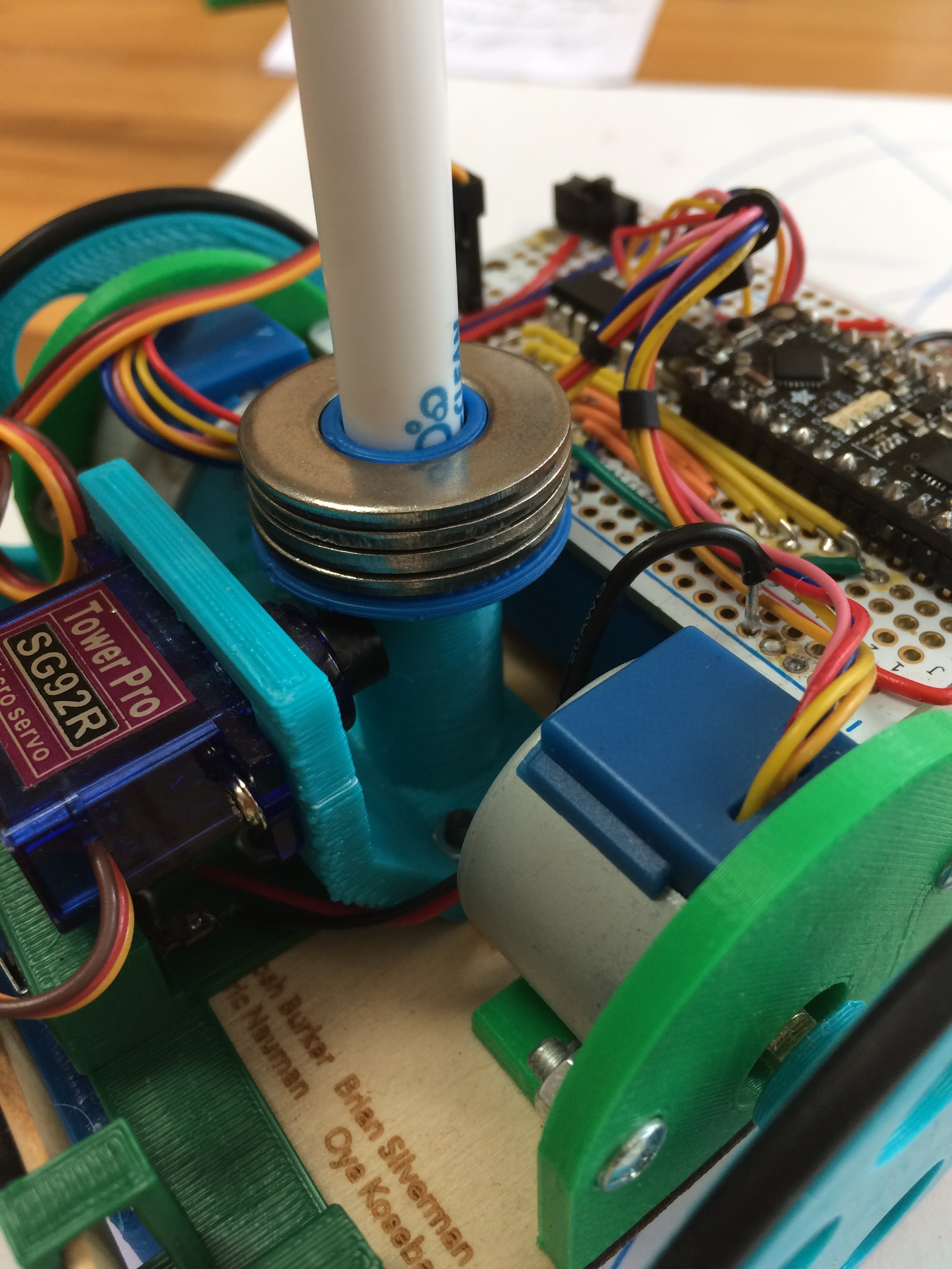
Adding 1/2 inch washers to the pen
holder provides enough weight to the pen that the pen does not shift
after the LogoTurtle changes directions. The result is crisper,
straighter lines and arcs.
Consider joining the LogoTurtle google group.
Thank you to Brian Silverman and Erik Nauman for helping this dream come true.
Thank you to Michael Tempel for an extra set of eyes on the documentation.
This work and images copyright 2017 Josh Burker